



A pneumatic diaphragm control valve uses compressed air and a flexible diaphragm to control or stop fluid inside pipes. You can easily learn how it works to keep your system running smoothly. This dependable control valve reacts quickly to keep your system balanced. At the same time, the strong pneumatic diaphragm valve setup keeps the fluid separated from moving parts. TANGGONG VALVE shares more than 36 years of valve making experience in this complete guide. You rely on an accurate pneumatic control valve to manage important job conditions like fluid flow, pressure, and temperature in tough factories every day.
Key Takeaways
-
Pneumatic diaphragm control valves use squeezed air to control liquid flow easily.
-
A stretchy inner diaphragm fully prevents dangerous fluids from reaching the moving engine parts.
-
Built-in steel springs automatically shift the valve to a safe position if the power goes out.
-
Air-powered systems stop dangerous electric sparks from happening in risky factory areas.
-
Bendable rubber and plastic diaphragms move harsh chemical liquids at average pressures.
-
Picking the right valve size using standard flow math helps the equipment last a long time.

Key Components of a Pneumatic Control Valve
You can understand how a pneumatic control valve works inside by looking at its main parts. Each part has a specific job to control fluid flow safely and correctly.
|
Component |
Contribution to flow regulation |
|---|---|
|
Valve body and bonnet |
Contain process flow and support the stem and packing, providing a safe flow path. |
|
Trim, stem, and control element |
The trim moves relative to the seat; the stem transmits actuator force to adjust flow openings. |
|
Diaphragm actuator |
Air pressure acting on the flexible membrane moves the stem to adjust flow openings. |
|
Positioner |
Compares control signal with valve position and adjusts actuator pressure for accurate flow modulation. |
|
Air supply accessories |
Deliver clean, regulated air to the actuator, ensuring reliable stem movement. |
|
Seals and packing |
Prevent leakage around the moving stem to maintain stable flow control. |
Pneumatic Diaphragm Actuator Assembly
Actuator Housing and Spring Return Mechanism
The pneumatic diaphragm actuator uses a simple design based on balanced forces. You send air pressure inside to move the inner parts into the right spot reliably.
-
Air pressure enters the actuator housing and pushes against one side of a flexible diaphragm.
-
The strong air pressure pushes the flexible diaphragm and the connected valve stem against a coiled spring.
-
The coiled spring pushes back to provide a set starting force for the valve.
-
The stem stops moving once the air force on the diaphragm equals the spring force.
-
The straight stem position changes evenly with input air pressure because the air directly controls the force.
This balance of forces makes an air operated pneumatic control valve react quickly when managing continuous processes.
Upper and Lower Air Chambers
A sturdy outer case holds the top and bottom air chambers safely inside. Compressed air enters the main working chamber to shift the flexible membrane. The opposite chamber holds strong coiled springs that push back. Changing the air pressure moves the stem smoothly, which keeps the system safe if power fails. A flexible pneumatic control valve reacts fast to automatic system directions.
Flexible Diaphragm Membrane and Stem
Elastomeric and PTFE Materials
You must pick flexible membranes that can handle rough process chemicals and hot temperatures. Synthetic rubbers like EPDM work well from -40°C to 120°C, while PTFE plastics handle tough temperatures from -60°C to 200°C. Neoprene runs from -23°C to 93°C, Nitrile works between -23°C and 88°C, and Viton operates from -40°C up to 177°C.
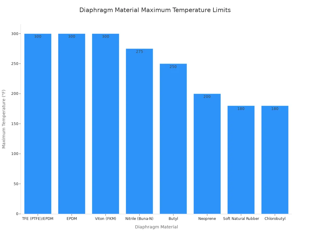
A tough diaphragm valve membrane keeps process liquids safely away from moving mechanical drive parts.
Stem Movement and Force Transmission
The valve stem acts as a direct metal connecting rod. This solid metal bar turns air pressure changes into smooth straight-line motion. The stem takes force from the membrane and pushes the inner compressor down to close the path or up to open it. Tight stem seals stop process liquids from leaking out during fast valve movements.
Valve Body Options and Internal Trim
Weir Type vs Straight-Through Body Designs
The body style changes how fluid moves through the inside of a diaphragm valve. The main shape controls the flow of liquid inside the control valve setup.
|
Selection point |
Weir type body |
Straight-through body |
|---|---|---|
|
Body geometry |
Raised weir saddle inside flow passage |
Open full-bore passage without saddle |
|
Flow path |
Restricted passage over raised weir |
Unobstructed direct flow path |
|
Pressure drop |
Generally higher |
Generally lower |
|
Flow capacity |
Limited by internal weir geometry |
Higher total flow capacity |
|
Solids handling |
Best for clean or controlled service |
Superior for slurries and suspended solids |
|
Drainability |
May retain small liquid amounts |
Excellent full drainage and flushing |
|
Diaphragm flexing |
Shorter stroke with lower flexing stress |
Deeper deflection stroke under pressure |
TANGGONG Control Valve Cage-Guided Trim Options
TANGGONG VALVE makes strong outer valve bodies using tough metals like ductile iron, WCB carbon steel, CF8 stainless steel, and CF8M stainless steel following ASME B16.34 standards. Every TANGGONG control valve uses smart cage-guided trim parts built right inside.
A round metal cage guides the inner plug to reduce shaking and help parts last longer. These internal trim options reduce loud noise, prevent bubble damage, and allow high liquid flow. TANGGONG VALVE covers every control valve stem and plug with hard SS316 stainless steel, Stellite 6, or tungsten carbide coatings to stop wear.
Combining high-flow trim parts with a pneumatic diaphragm actuator ensures steady working accuracy over time. A calibrated TANGGONG control valve keeps process levels steady even under tough factory conditions.
Operating Principles of the Pneumatic Diaphragm Valve
Air Pressure and Spring Balance Mechanism
You can learn how this machine works by looking at forces balancing inside the main housing. A pneumatic diaphragm control valve uses air pressure pushing against strong springs to move an inner plug to the right spot.
Conversion of Air Signals into Linear Travel
Air systems change pressure into straight movement. You send clean air inside the top or bottom room of the actuator. Air pushes against a flexible membrane. The membrane then squeezes steel springs to move the stem in a straight line.
-
The air pressure given to the actuator matches the force range of its built-in springs.
-
A common spring setup uses air pressure between 0.2 and 1 bar to operate smoothly.
Proportional Response to Control Air Signals
Inner springs push back against the stem with a set amount of force. Every small shift in air pressure moves the stem an equal distance. Because of this force, tiny pressure changes make the stem adjust very smoothly.
Positioners keep the stem in the right spot by matching input air signals to real stem movement. The simple chart below shows how two main positioner types set the valve position.
|
Mechanism |
Air pressure & spring/beam balance action |
How valve position is determined |
|---|---|---|
|
Force-balance pneumatic positioner |
A small 3-15 psi air signal moves a metal beam to close a small air nozzle. The valve stem connects to this beam through a spring. The shifting nozzle pressure changes air force on the diaphragm. |
Balance happens when the signal force equals the spring force, holding the stem in its set position. |
|
Motion-balance pneumatic positioner |
A rising air signal shifts the beam toward the nozzle to build up backpressure. An air relay then sends more pressure to the actuator. The moving stem pushes back on the beam. |
When the beam movement matches the stem feedback push, the valve stops and holds its steady position. |
Direct vs Reverse Acting Fail-Safe Modes
Factory safety rules tell you which actuator type to pick if air pressure drops during emergencies. These smart fail-safe designs use spring force to push the plug back into a safe state. You pick a good valve setup based on factory safety needs.
Air-to-Open Configuration (Fail-Closed)
An air-to-open pneumatic diaphragm valve needs positive air pressure to open up the pipe. Strong springs automatically push the plug closed if air supply cuts off. Fuel lines use these air-to-open valves so fuel stops flowing during emergencies to keep plants safe.
Air-to-Close Configuration (Fail-Open)
An air-to-close valve uses air pressure to close the flow path against spring force. Strong springs push the plug open when air pressure drops down to zero. Water lines use these air-to-close valves so cooling water keeps flowing to stop equipment from overheating.
|
Configuration |
Behavior as air pressure increases |
Position on loss of air |
Fail-safe designation |
|---|---|---|---|
|
Air-to-open (ATO) |
Opens step by step |
Closed |
Fail-closed (FC) |
|
Air-to-close (ATC) |
Closes step by step |
Open |
Fail-open (FO) |

Positioners and Signal Integration
Modern factories connect every air operated pneumatic control valve directly to main computer networks. You can use smart positioners to adjust flow and change electric signals into mechanical stem movement.
4–20 mA and Digital Electro-Pneumatic Controls
An electro-pneumatic positioner controls a pneumatic control valve by turning electric current into matching air pressure. You can connect 4–20 mA signals from factory computers to the diaphragm valve to make flow control better.
-
The positioner gets a 4–20 mA signal where 4 mA means closed and 20 mA means fully open.
-
A sensor checks the real valve spot all the time.
-
The positioner compares the signal to the valve spot and finds any small error.
-
Computer logic decides to open or close the valve to fix the error.
-
The positioner changes air pressure inside the actuator to move the valve to the target spot.
-
This quick loop repeats nonstop to keep control valve positioning accurate.
HART, Modbus, and Profibus Protocol Support
Smart digital positioners work with modern factory communication networks. You can check diagnostic health, opening speed, and tight seal safety from far away using HART, Modbus, or Profibus links. These digital tools send live signals right to your control room screens. You fix tiny tuning problems early and help the diaphragm valve last much longer.
Applications of the Pneumatic Diaphragm Control Valve
Chemical Processing and Corrosive Media
Isolation of Aggressive Acids and Solvents
Chemical processing plants move strong acids, caustics, and solvents through pipes every day. You rely on a pneumatic diaphragm valve to keep dangerous fluids safely inside the pipe. The inner elastomeric or plastic membrane completely seals off the top bonnet assembly. This solid barrier stops harsh chemicals from touching inside mechanical drive parts.
Corrosive liquids quickly ruin standard metal parts inside regular flow devices. Plastic body linings and matching elastomeric seats resist strong chemical attacks very well. Standard chemical pipes benefit greatly from a flexible diaphragm valve setup. An air-operated valve isolates harsh media completely, which protects plant workers and surrounding factory gear.
Refining, Petrochemical, and Energy Sector
High-Pressure and Extreme Temperature Service
Refining plants operate under tough conditions with steam, hot oil, and volatile chemicals. You need a tough control valve to handle big process changes smoothly. Special body builds handle high pressure differences and extreme heat cycles in power plants.
Pneumatic control equipment works within a pressure range from 0 to 150 psig. Standard pneumatic options operate from -20°F to 123°F, while low-temperature models run safely from -40°F to 123°F. You can also pick strong body metals for hot oil or hot steam lines. The safe pneumatic diaphragm control valve stays in a safe spot during emergency shutdowns.
Water Treatment and Slurry Handling
Managing Viscous Fluids and Abrasive Suspensions
Water treatment plants process raw river water, lime slurries, and harsh treatment chemicals. You can trust a diaphragm valve to handle thick liquids without clogging inside paths. Smooth inner body paths let solid bits flow cleanly through the body. Sewage treatment systems use a pneumatic diaphragm valve to manage rough chemical slurries safely.
Thick liquids and rough bits often cause bad wear inside common control valves. Flexible membrane seats push firmly over trapped solid bits to seal off tightly. Workers easily connect a modern control valve unit into automated water systems. This strong design gives steady flow control and lasts longer in heavy slurry handling.
Pros and Cons of a Diaphragm Valve System
Key Operational Advantages
Complete Hermetic Sealing to Prevent External Leakage
A glandless diaphragm valve creates a solid seal against leaks in chemical flow pipes. The flexible membrane keeps fluid separated from the upper drive parts inside the valve body. A synthetic PTFE diaphragm clamps tightly between the body and bonnet to seal the valve. This smart design isolates the upper parts to keep them safe, clean, and dry.
The flexible membrane pushes down directly on the inner weir to stop flow without stem seals. This setup removes mechanical gaps that could leak liquid outside over time. A standard diaphragm valve stops dangerous chemical leaks and keeps your plant safe. Workers avoid exposure because fluid cannot escape through moving stem seals into open air.
Intrinsically Safe Pneumatic Operation in Hazardous Zones
Air pressure powers the system so you can avoid using electric parts. This simple air setup reduces spark risks and easily meets strict ATEX and IECEx safety standards. Small actuators push with strong force to give you fast stem movements and accurate control. You can safely place this air control system into dangerous factory locations.
Air operated tools work reliably without any electric noise during big temperature shifts. Using clean compressed air instead of hydraulic fluid prevents messy oil leaks in your plant. Strong valve builds reduce overall maintenance, lower long-term costs, and keep your factory running safely.
Technical Limitations
Temperature Bounds of Synthetic Diaphragm Polymers
Synthetic polymers break down faster in hot liquids than solid metal components. You must check liquid temperatures carefully to stop soft inner membranes from tearing apart inside pipes. Always review exact heat limits before placing a pneumatic diaphragm valve into hot chemical processes.
|
Diaphragm polymer |
Operating temperature range (°F) |
|---|---|
|
Neoprene |
-20 to 200 |
|
Butyl rubber |
-4 to 248 |
|
Nitrile rubber |
-14 to 134 |
|
Viton (fluorocarbon) |
-20 to 300 |
|
EPDM |
-20 to 230 |
|
PTFE (Teflon) |
-300 to 3000 |
These clear heat limits show safe working ranges for synthetic diaphragm polymers in factory pipes.
Pressure Rating Constraints Compared to Metal Seated Trim
Soft rubber and plastic parts can bend out of shape under high liquid pressure. Strong pressure spikes stretch synthetic membranes past their limit, which shortens overall part life over time. High fluid forces damage non-metal pieces much faster than hard steel components.
Metal-seated valves withstand heavy pressure spikes far better than flexible rubber seats. Picking the right control valve protects your system from damage in high-pressure lines. A flexible diaphragm valve works best when managing fluids at low or medium line pressure.
Selecting a TANGGONG Control Valve Solution
Engineers choose proper valve sizes to ensure long plant life and stable system operations. TANGGONG VALVE helps you select the correct control valve for your specific piping conditions.
Process Fluid and Sizing Standards
IEC 60534 Sizing Calculations and Flow Capacity
Standard sizing uses ANSI/ISA-75.01.01 (IEC 60534-2-1 Mod) equations to calculate required flow coefficients. You size a pneumatic diaphragm control valve so it operates around 60–80% open at maximum flow. The valve should also stay above 20% open during minimum flow.
|
Sizing factor |
Evidence from IEC 60534/ISA-75.01.01 |
|---|---|
|
Standard basis |
ANSI/ISA-75.01.01 provides the flow equations for valve sizing. |
|
Flow capacity |
For liquid flow, the ideal equation is Q = Cv × sqrt(dP / Sg). |
|
Choked flow |
Liquid flow chokes when pressure drops below vapor pressure. Gas flow chokes at sonic velocity. |
|
Correct valve size |
Calculated Cv selects a valve with adequate capacity to prevent poor control. |
An undersized control valve blocks fluid flow. An oversized unit creates system instability. TANGGONG VALVE provides free IEC 60534-compliant sizing calculations to help your team choose correctly.
Pressure Class Considerations (Class 150 to Class 2500)
Piping systems operate across different pressure levels. TANGGONG builds valve bodies ranging from Class 150 up to Class 2500 (PN10 to PN420). You can select carbon steel WCB or stainless steel CF8 and CF8M materials for tough conditions.
TANGGONG engineering adapts every diaphragm valve unit to work across temperature ranges from -196°C to 650°C. Robust material certifications ensure safe fluid containment in severe operations.
Shutoff Performance and Quality Certifications
ANSI/FCI 70-2 Leakage Standards (Class IV, V, VI)
Shutoff performance determines internal seat leakage during full closure. TANGGONG designs trim assemblies to match strict ANSI/FCI 70-2 shutoff classes.
|
Class |
Seat material |
Maximum allowable leakage |
Test medium & pressure |
Typical application |
|---|---|---|---|---|
|
IV |
Metal-to-metal |
0.01% of rated Cv |
Air or water at 50–60 psi |
General process control |
|
V |
Lapped metal with Stellite |
0.0005 mL/min per inch of port diameter per psi |
Water at max operating pressure differential |
High-pressure drop steam |
|
VI |
Soft seat (PTFE/elastomer) |
Measured in bubbles per minute (e.g., 1 bubble/min for 2-inch valve) |
Air or nitrogen at 50 psi |
Toxic gas, tight shutoff |
Every control valve meets targeted shutoff needs reliably.
ISO 9001:2015, CE, and API Quality Compliance
TANGGONG manufactures every pneumatic control valve under ISO 9001:2015 quality control management. Factory technicians calibrate each unit before shipment to guarantee immediate site startup.
Products comply with CE standards and undergo hydro-testing per API 598. TANGGONG offers SIL-capable control valve builds certified for critical safety loops. This complete quality assurance gives you total peace of mind for your plant operations.
A pneumatic diaphragm control valve converts compressed air signals into linear stem movement. This simple action provides accurate flow throttling and reliable hermetic isolation for your piping systems. You maintain high plant safety and process stability when you select the correct setup. Choosing the right air-to-open or air-to-close actuator action ensures dependable fail-safe performance during power loss. Selecting durable single-seated trim and compatible EPDM or PTFE membrane materials prevents premature wear inside a pneumatic diaphragm valve. You can explore TANGGONG VALVE's full range of ISO 9001 and CE-certified control valve solutions today or request a free IEC 60534 valve sizing consultation with our expert engineers.
FAQ
What is the main difference between a control valve and an isolation valve?
A control valve keeps tweaking fluid flow, pressure, or heat using partial turns. An isolation valve simply opens wide or shuts tight to start or stop liquid entirely.
Why do you use compressed air to power the actuator?
Compressed air gives you quick movement and safe power in dangerous work areas. Pneumatic actuators stop electrical spark risks and give safe action during power outages.
How does a pneumatic diaphragm valve keep internal parts clean?
A flexible membrane shields moving parts by blocking direct contact with fluid. This strong physical barrier stops harsh chemicals from reaching the upper drive parts.
What fail-safe modes can you select for your system?
You select an air-to-open setup for fail-closed or air-to-close for fail-open setups. Built-in springs quickly push the stem into a safe spot if air pressure cuts off.
How do you select the correct valve size for your application?
You find the flow capacity using clear IEC 60534 industry rules. Right sizing keeps fluid moving smoothly while the valve stays open between 20% and 80%.
Which temperature limits apply to TANGGONG valve units?
TANGGONG engineers build valve units to handle very tough factory conditions. Smart material picks help every valve setup run safely from -196°C up to 650°C.
Which certifications back TANGGONG quality standards?
TANGGONG makes valve parts under approved ISO 9001:2015 quality control systems. Workers check leak protection using ANSI/FCI 70-2 rules and run water tests under API 598.