



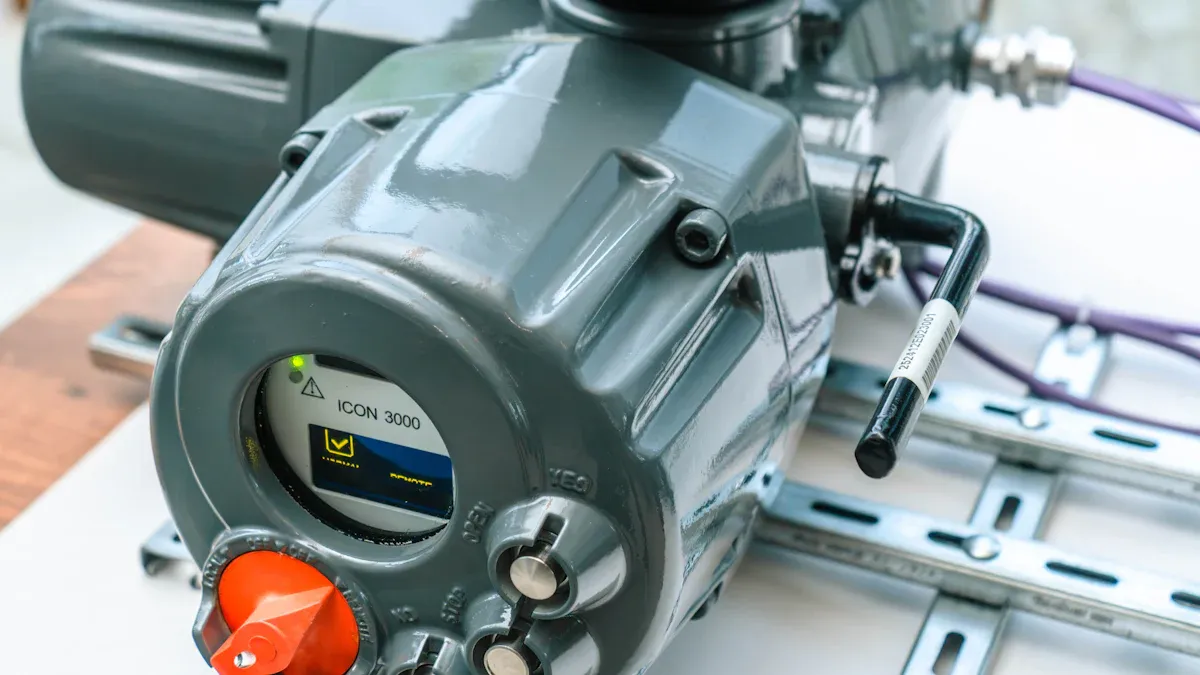
A pneumatic control valve acts as an automatic helper in modern factory systems. It uses squeezed air to adjust liquid flow, pressure, or temperature with great accuracy. You rely on these strong machine parts to keep exact control over tough liquid and gas pipes. Learning about this key control technology helps you boost factory safety, lower repair costs, and improve overall work output. You will look at the main physical parts that make the valve work well. You will also learn the step-by-step process, key types, and main benefits needed to pick dependable valve options for tough factory jobs.
Key Takeaways
-
Pneumatic control valves use trapped air under pressure to change liquid flow, pressure, and heat on their own.
-
Continuous throttling valves change fluid flow smoothly, while simple isolation valves only open or close all the way.
-
Built-in actuator springs automatically move valves to safe positions if air pressure drops suddenly.
-
Positioners change electrical signals into air pressure to move the valve stem with great accuracy.
-
Cage-guided trims lessen inner plug shaking, lower liquid noise, and protect valves from sudden damage.
-
Air-powered actuators work safely in dangerous factory areas without creating risky electrical sparks.
-
Smart digital positioners send live health data to main control rooms for simple maintenance tracking.
Understanding the Pneumatic Control Valve
Definition and Core Function
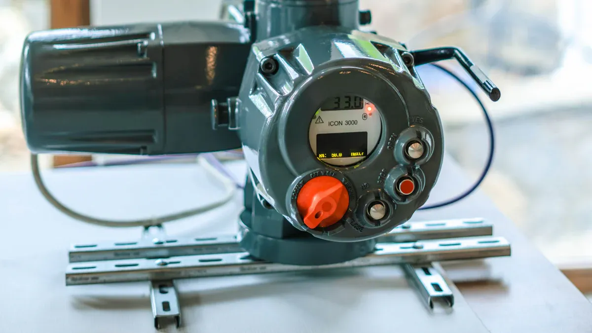
You rely on special equipment to manage liquids, steam, and gases inside factory pipes. A pneumatic control valve acts as a powered control tool. It uses compressed air to change the exact size of an internal opening. By altering this internal flow space, the device adjusts key system conditions like fluid movement, line pressure, and overall temperature.
You can understand its main job by checking how it works inside a continuous loop:
-
The controller compares a measured process variable with your target value and sends a positioning signal, like a 3–15 psi pneumatic signal or a 4–20 mA electronic signal.
-
An electro-pneumatic positioner converts electronic signals into proportional air pressure to push a diaphragm or piston actuator.
-
The actuator moves the valve stem, altering the flow area between the plug and seat to change fluid flow rates directly.
-
The positioner constantly checks the real stem position against the target position and adjusts air pressure to hold any middle opening.
-
Sensors in your system measure updated flow, pressure, or temperature values and send data back to the controller, finishing the continuous loop.
Role in Industrial Automation
Modern manufacturing plants operate constantly all day and night. You cannot turn manual valve handwheels fast enough to keep tight system limits. Automated valve setups react right away to small pipeline changes. They protect product quality and work efficiency across oil refining, chemical processing, and power generation plants.
These automated control setups also boost safety across your plant. Actuators use specific air-to-open or air-to-close mechanical setups. If your plant suffers a sudden loss of air pressure, heavy return springs push the stem into a set safe position. This quick fail-safe action stops overpressure events and guards plant workers from dangerous fluid leaks.
Continuous Throttling vs. On-Off Isolation
You must pick correct valve styles based on your specific system control needs. Standard isolation valves offer simple on-off service. They stay wide open to allow maximum fluid flow, or they close fully to stop movement. Engineers use these isolation tools mainly for equipment shut-off during plant repair work or emergency shut-down actions.
In contrast, a pneumatic control valve offers continuous throttling control to keep exact steady conditions. It moves stem parts to any position between fully open and fully closed. You can compare the main operational differences between these valve choices in the table below:
|
Feature |
Continuous Throttling |
On-Off Isolation |
|---|---|---|
|
Primary Function |
Precise flow variable modulation |
Basic fluid flow shut-off |
|
Stem Movement |
Infinite intermediate positions |
Fully open or fully closed |
|
Control Input |
4–20 mA or 3–15 psi signal |
Simple binary control signal |
|
System Value |
Constant process parameter stability |
Complete pipeline fluid isolation |
Essential Components of TANGGONG Control Valves
TANGGONG VALVE builds every pneumatic control valve with high engineering standards. You can choose from proven metal alloys to match specific pipeline requirements. Common valve body materials include cast carbon steel like WCB, alloy steels like WC6 and WC9, and stainless steel grades like CF8, CF8M, CF3, and CF3M. You can also select low-temperature steels like LCB and LCC for cold fluid lines. Inner trim components use durable stainless steels like SS304, SS316, and SS316L, or hardened materials like 17-4PH, Stellite 6, and Tungsten Carbide.
The Valve Body Assembly
Flow Passage and Body Materials
You rely on the valve body assembly to contain high process pressures and direct fluid flow safely. Engineers size these passages according to IEC 60534 sizing requirements. TANGGONG VALVE manufactures body sizes ranging from DN15 to DN600 (½" to 24") and handles pressure classes from Class 150 to Class 2500 (PN10 to PN420). The robust metal casing handles extreme fluid temperatures from -196°C to 650°C without cracking or warping.
Cage-Guided Trim and Seat Design
You gain superior flow management with cage-guided trim designs. The cylindrical cage features precision-machined ports that guide the moving valve plug smoothly inside the body. This structure reduces mechanical vibration, lowers operating noise, and prevents cavitation damage in high-pressure fluid drops. The valve seat design controls internal fluid leakage according to ANSI/FCI 70-2 shutoff standards.
TANGGONG VALVE designs and tests valve seats to meet ANSI/FCI 70-2 Class IV, Class V, and Class VI shutoff standards, ensuring minimal seat leakage during complete closure.
Pneumatic Actuator Types
Pneumatic Diaphragm Actuators
You use pneumatic actuators to convert air pressure into mechanical stem motion. A diaphragm actuator uses a flexible membrane sealed inside a metal housing. You can compare the key differences between diaphragm and piston actuators using the following table:
|
Aspect |
Diaphragm Actuator |
Piston Actuator |
|---|---|---|
|
Thrust |
Operates at lower air pressures (typical maximum 60 psi) and requires a larger surface area to generate high force. |
Operates at higher instrument-air pressures up to 150 psi, delivering greater thrust density within a compact footprint. |
|
Stroke Length |
Provides limited stroke length, making it ideal for short travel and fast response. |
Supports extended stroke lengths with consistent bidirectional motion for long-travel valve applications. |
|
Failure Mode |
Uses an inherent spring-return mechanism for simple fail-safe action without external air tanks. |
Achieves fail-safe operation using internal springs or air volume tanks, and allows easy field reversibility. |
Pneumatic Piston Actuators
You choose piston actuators when your system demands extreme stem force or longer travel distances. Piston actuators replace the rubber membrane with a solid piston moving inside a rigid cylinder. High supply pressures push the piston quickly, giving you firm control authority against heavy fluid forces inside large pipelines.
Positioners and Control Accessories
You maintain exact valve stem positioning by adding digital accessories to your actuator assembly. Electro-pneumatic positioners read 4–20 mA electrical signals or digital fieldbus commands, including HART, Modbus, and Profibus options. You can understand how positioners, boosters, and air regulators upgrade performance through these targeted functions:
-
Electro-pneumatic positioners compare input signals with actual stem positions, feeding or exhausting air to eliminate positioning errors caused by stem friction.
-
Air volume boosters deliver extra air volume to the actuator, speeding up valve full-stroke movement across large valve bodies.
-
Air filter regulators clean and regulate incoming supply air, preventing moisture and dirt particles from clogging sensitive positioner components.
Operating Mechanism of a Pneumatic Control Valve
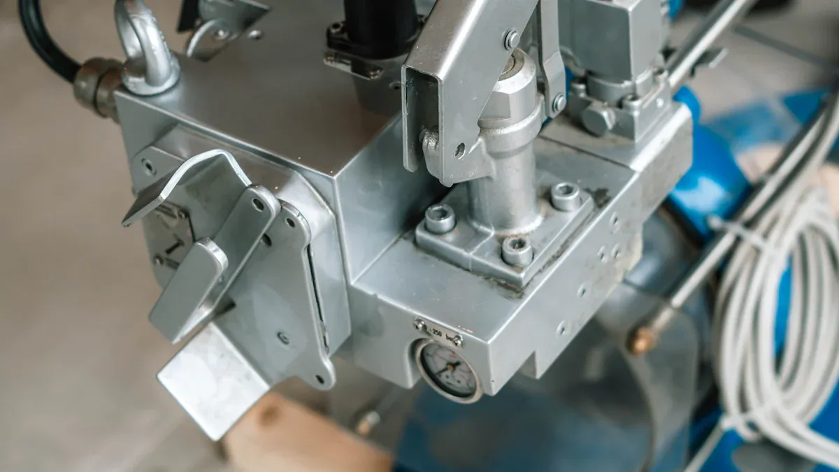
You depend on automated tools to control fluid lines smoothly. A pneumatic control valve changes electronic signals into real physical movement inside your pipe system. This action works through exact air pressure changes, balance of forces, and steady stem movement.
Air Signal Input and Pressure Response
You can follow how signal inputs change fluid flow through these five steps:
-
The controller compares system data to your target value and sends a signal using a 4–20 mA current or air pressure.
-
An electro-pneumatic positioner takes this signal and changes it into matching air pressure inside the actuator.
-
The pressurized air pushes a flexible diaphragm or solid piston, which moves the attached valve stem.
-
As the stem moves, it changes the space between internal trim parts like the plug and seat.
-
This new trim location changes the open flow area, adjusting fluid movement to match your target value.
Global engineering rules set clear operational criteria for these actuation parts. You can check main rules from top standards listed in the chart below:
|
Standard |
Technical Scope and Operational Guidance |
|---|---|
|
ANSI/ISA-96.01.01-2026 |
Standardizes actuator terms and key operating traits for system response tests. |
|
ANSI/ISA-96.03.01-2026 |
Covers heavy-duty scotch yoke rules and standard factory testing steps. |
|
ANSI/ISA-96.03.02-2024 |
Details air supply rules, turning force, and control methods for rack and pinion builds. |
|
ANSI/ISA-96.03.03-2025 |
Gives helpful rules on control choices and working traits for vane actuators. |
|
ANSI/ISA-96.03.04-2019 |
Sets exact work settings and mounting sizes for straight piston actuators. |
Engineers test actuator speed with digital timers, fast cameras, and special tools during factory checks. You can speed up movement times by improving airflow, smoothing out moving parts, and using smart control units.
Force Balance and Spring Action
Your actuator works through a steady balance of pushing forces. Compressed air pushing on the diaphragm surface creates driving force. You find this total push using a simple formula where actuator force equals air pressure multiplied by diaphragm area. Larger surface areas or higher air pressures create much stronger stem movement.
Built-in springs push back with equal force against stem movement. These springs resist movement until higher air pressure squeezes them further down. The moving valve plug stops at a stable spot when downward air push equals opposing spring force and liquid pressure. Changing incoming air pressure resets this balance, moving the stem to match your input signal.
Air-to-Close Spring-to-Open Action
You use fail-open setups when plant safety needs open flow during total air power losses. This process moves through simple steps:
-
High-pressure air enters the top actuator chamber right above the flexible diaphragm.
-
Increasing air pressure presses down on internal springs and pushes the diaphragm downward.
-
The moving diaphragm pushes the stem lower, pressing the plug against the seat to block fluid.
-
Letting air out allows springs to uncoil, lifting the stem up to open the valve line.
Air-to-Open Spring-to-Close Action
You pick air-to-open setups to keep downstream equipment safe from liquid overflows. Supply air moves into the bottom actuator room below the diaphragm. Increasing air pressure compresses the top springs, lifting the stem to open the flow path. If main air fails, compressed springs push the stem down fast, seating the plug to stop fluid flow.
Stem Movement and Flow Regulation
Stem height sets overall valve flow power, measured as flow coefficient Cv. One Cv unit means one US gallon of water flows every minute through the valve with a 1 psi pressure drop. You find flow capacity using the standard formula Cv = Q x sqrt(SG / ΔP), where Q is flow rate in GPM, SG is specific gravity, and ΔP is pressure drop in psi.
Flipping this equation around shows the flow calculation Q = Cv x sqrt(ΔP / SG). As your pneumatic control valve raises its stem, flow openings grow wider and Cv increases. You get smooth, accurate system control by running the valve stem between 20% and 80% open travel.
Classifying Pneumatic Control Valves by Function
Directional Control Valves
You use directional valves to guide air to different actuator ports. Standard rules like ISO 1219-1:2012 define symbols for these tools. Factories also follow ISO 15407 rules to keep all valve setups safe and matching.
You pick port and position setups based on what actuators need. A 2/2 valve has two ports for basic on-off air control. A 3/2 valve moves air to run single-acting spring cylinders. A 5/2 valve has five ports to move double-acting cylinders with two separate exhausts.
Flow Control Valves
You set up flow control valves to change air speeds and actuator motion. Squeezing actions change the size of the inside opening. Control units send signals to move valve stems and match target flow rates.
A valve's power to control flow depends on its Cv rating. This value shows how much water flows through a wide-open valve during a set pressure drop. Changing flow speeds helps keep system settings steady as line pressures change.
Linear Flow Characteristics
You pick linear flow features when system pressure drops stay very steady. Flow rates change in direct step with stem travel distance. Moving a stem halfway lets through exactly half of the total fluid flow.
This clear style makes it easy to set up basic liquid systems. You control fluid amounts directly without needing extra signal changes. System conditions stay safe and steady during normal work operations.
Equal Percentage Flow Characteristics
You pick equal percentage setups for systems with shifting pressure drops. Moving the stem by equal steps changes the flow rate by equal percentages. Small stem moves near the bottom make very tiny flow changes.
Larger stem travel near the top creates much bigger volume changes. This action keeps pipeline pressure balanced across your system. You get exact fluid control even when operating conditions vary greatly.
Pressure Control and Relief Valves
You rely on pressure valves to control line pressure and protect hardware. Pressure reducers keep outlet levels steady when inlet values change. Backpressure units open to fix upstream levels if inlet limits get too high.
Pressure relief valves act as safety tools against sudden pressure spikes. These protective tools open automatically when pressure gets unsafe, releasing fluid to guard your team and gear. Special relief valves open slowly and close smoothly when pressure drops.
Signal Integration and Actuation Options
Direct Air Signal Control
Direct air signal control uses pure pneumatic pressure to operate your valve without electrical power. A central pneumatic controller sends air pressure through small tubing lines directly to the valve actuator. The standard setup uses a pressure range of 3–15 psi to command full valve movement. This method offers complete explosion safety in hazardous plant zones because it contains no electrical ignition sources.
You can split this control pressure range to drive two separate valves from one central controller. A split-ranging setup sends a 3–9 psi pressure signal to move the first valve. The controller then uses a 9–15 psi air signal to operate the second valve. Direct air systems lower initial component costs, reduce electrical wiring failures, and simplify basic system maintenance in harsh plant environments.
Electro-Pneumatic Signal Conversion
Modern automated plants rely on electronic controllers to process complex system data quickly. An electro-pneumatic current-to-pressure transducer acts as the practical interface between electrical commands and mechanical movement. This transducer receives a standard 4–20 mA current signal from your central control system. It converts that electrical input into proportional pneumatic pressure, ranging from a few psi to over 100 psi, to push the actuator diaphragm.
Manufacturers often integrate this transducer directly into an electro-pneumatic positioner to boost stem positioning accuracy. The positioner follows a quick four-step control sequence:
-
The positioner receives the 4–20 mA current command as the target valve location setpoint.
-
A physical feedback sensor measures the real stem position and compares it with the setpoint command.
-
Internal control logic calculates the required correction and adjusts air pressure supplied to the actuator.
-
The actuator moves the valve stem until pressure force and spring force balance at the exact setpoint location.
Smart Digital Communication Protocol Integration
Smart digital positioners upgrade standard signal conversion by adding two-way digital communication protocols. You can connect these intelligent positioners to digital networks using HART, Modbus over RS-485, or PROFIBUS protocols. The HART protocol superimposes a digital signal over the traditional 4–20 mA loop. This design allows your control room to read process variables, internal device settings, and calibration data simultaneously over a single wire pair.
Digital fieldbus networks give your engineering team deep operational visibility into real-time valve health. Smart positioners continuously monitor high-resolution stem position, total stem travel, calculated packing friction, and actuator air pressure. Advanced fieldbus protocols can push timestamped event data at high speeds between 20–100 Hz directly to your plant asset management system. These predictive diagnostic analytics help your engineering team spot early calibration faults, schedule proactive maintenance, and prevent unexpected plant shutdowns.
Benefits of Choosing TANGGONG VALVE
TANGGONG VALVE runs a top-quality factory in Wenzhou, China. The business supports factories worldwide through careful testing and fresh engineering ideas. TANGGONG VALVE owns more than 200 total patents along with major global quality seals.
|
Aspect |
Details |
|---|---|
|
Quality Certifications |
ISO 9001:2015, CE, TUV, SGS, API 6D, API 607 |
|
Patent Portfolio |
20 independent patents, 200 national patents |
|
Technical Services |
Free IEC 60534-compliant valve sizing consultations |
You can ask skilled engineers for free valve sizing help that meets IEC 60534 rules. This helpful service lets you pick ideal gear for oil, gas, power, and ship jobs.
Safe Performance in Dangerous Areas
You keep your plant safe by using dependable spring-return drive units. Strong inside springs push the valve stem to a safe spot if air drops or power cuts out. You can order air-to-close builds to clear out hot pipes during emergencies. You can also pick air-to-open setups to block dangerous, toxic, or flammable fluids right away.
Your workplace stays protected around explosive gas or fine dust clouds. TANGGONG VALVE makes drive units that pass strict ATEX, IECEx, and safety area test rules. These designs also share proven safety check records for easy plant setup. You can easily connect these parts to SIL 2 and SIL 3 emergency safety setups.
Fast Actions and Strong Push Power
Pneumatic drive units give strong pushing force and fast action speeds inside small metal frames. You can adjust opening times easily with simple air flow valves. Unlike electric motors, air-powered units can hold heavy stops indefinitely without burning out internal coils or pulling extra wall power.
|
Aspect |
Pneumatic Actuator |
Electric Actuator |
|---|---|---|
|
Response and Speed |
Delivers fast cycle speeds; adjustable using simple air speed-control valves |
Fixed cycle speed; speed changes require internal physical gearing replacements |
|
Stalling Capability |
Stalls indefinitely under load without overheating or motor damage |
Stalling draws excessive current and damages internal motor components |
You can hook these valve setups right into modern control stations without losing data speed. The positioners read common 4–20 mA current inputs. They also read smart computer signals like HART, Modbus, and Profibus.
Long Life in Harsh Working Conditions
Tough system jobs expose inside valve parts to sharp pressure drops and rushing liquids. Smart cage-guided trims hold internal parts steady as fluids pass through the valve body. The protective cage slides the plug smoothly to stop shaking and cut down on rough fluid swirling.
Makers add tough Stellite 6 alloy layers onto stainless steel seat parts. Stellite 6 creates a rock-hard shield that tests between 36 and 45 on the HRC scale. This outer shield absorbs rough impact energy from collapsing bubbles. This tough build guards your valve against heavy rubbing and wear, giving you many years of solid use.
A pneumatic control valve uses compressed air to deliver precise throttling control across your factory pipelines. Your automated system relies on exact pressure signals to adjust fluid flow, line pressure, and process temperature continuously. You protect your plant equipment by selecting the proper actuator, trim style, and body materials. Matching these vital components directly to your working pressure, fluid temperature, and chemical media prevents early wear and costly plant downtime.
TANGGONG VALVE manufactures high-performance pneumatic control valve solutions engineered for ultimate safety, operational efficiency, and long industrial durability worldwide. You can trust our certified engineering expertise to keep your critical process operations running safely every day.
FAQ
What is the main difference between a control valve and an isolation valve?
A control valve handles smooth, ongoing flow changes using electronic signals. An isolation valve just provides basic on-off service. It stays completely open or closed to start or stop liquid movement.
Why do you use pneumatic control valves in hazardous plant areas?
Pneumatic actuators use air power instead of electricity, removing spark dangers in explosive spaces. Built-in springs also slide the inner rod to a set safe spot if air pressure fails.
What is the primary purpose of cage-guided trim inside a control valve?
Cage-guided trim uses a hollow metal tube with shaped openings to guide the moving plug smoothly. This design cuts down liquid noise, stops shaking, and protects heavy pipes from wear.
How do you size a pneumatic control valve for your application?
You pick the right valve size by checking your liquid type, target flow rate, line heat, and pressure drops. TANGGONG VALVE offers free advice using official IEC 60534 rules to help you choose.
Which control signals do smart pneumatic positioners support?
Smart positioners turn standard 4–20 mA electrical signals into accurate air push force. They also support digital networks like HART, Modbus, and Profibus to send health reports back to your main office.
What quality certifications do TANGGONG control valves carry?
TANGGONG control valves hold major quality approvals, including ISO 9001:2015, CE, and SGS seals. Each valve build follows IEC 60534 rules and meets clear ANSI/FCI 70-2 tightness standards.