



A flow control valve is a part that controls how fast or how much fluid moves through a system. You need this control to manage pneumatic actuators like cylinders, keeping machine operation smooth and safe. Ever wonder how a pneumatic cylinder moves at a steady pace instead of slamming forward? The answer lies in this small but critical part.
Without proper flow control, you face several issues:
-
Cylinders move too fast, damaging themselves or nearby tooling
-
Loud pneumatic actuation occurs
-
Abrupt operation happens at power-up
-
Inconsistent cylinder speed leads to inconsistent strokes
This article explains the mechanics, looks at different types, and gives practical tips for choosing the right flow control valve for your needs.
Key Takeaways
-
Flow control valves manage how fast fluid moves in pneumatic and hydraulic systems.
-
A variable orifice inside the valve adjusts the flow rate by altering the opening size.
-
Needle valves allow very exact flow control, which is perfect for fine-tuning tasks.
-
Flow control valves with check valves let you control speed in one direction, while allowing free flow in the other.
-
For pneumatic cylinders, use meter-out control to make sure the motion is smooth and stable.
-
Choose the correct valve size (Cv) so it fits your system's flow needs.
-
Installing and adjusting correctly can prevent common problems like jerky motion and wearing out too soon.
How a Flow Control Valve Works
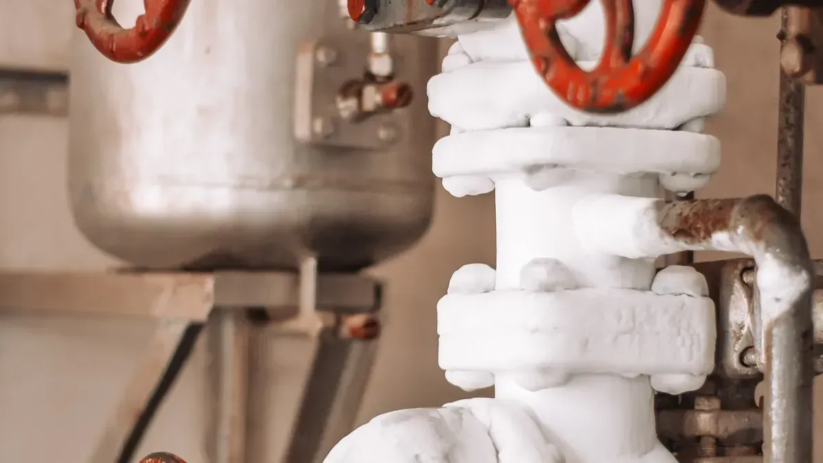
Every flow control valve works on a simple idea. Change the size of the path, and you change how much fluid moves through. This path is called an orifice. It acts like a gate. Open it wide, and fluid flows fast. Close it down, and you slow the flow. The whole science of flow control is about this adjustable opening.
The Core Mechanism: A Variable Orifice
Think of a garden hose. When you put your thumb over the opening, water shoots out faster but less flows. A flow control valve does the same thing, but with more control. Inside the valve, a tapered stem moves against a matching seat. This creates a variable orifice. You can adjust it from fully closed to fully open.
The variable orifice works by changing the gap between the needle and its seat. This directly changes the flow rate through the valve. But in a system with a fixed pump, just adjusting the orifice does not always change the flow rate. You need a way to reduce or bypass the flow that would otherwise be forced through the valve. The fluid must go somewhere.
How a Needle Valve Creates a Restriction
The needle valve is the simplest example of this idea. Its name comes from the shape of its internal stem. The stem tapers to a fine point like a sewing needle. This needle fits into a precisely machined seat.
-
The adjustment screw is tapered at its end. It controls the size of the passage opening.
-
Turning the screw clockwise makes the passage smaller. This increases air resistance.
-
Turning the screw counterclockwise makes the passage larger. This reduces air resistance.
-
This variable resistance directly controls the airflow rate. It lets you adjust actuator speed precisely.
When you turn the knob, the needle moves closer to or farther from the seat. This changes the gap between them. A small turn gives a small change. That precision makes needle valves great for fine-tuning.
The needle valve controls flow by changing the gap between the needle and the valve seat. This directly controls the cross-sectional area for air passage.
The Relationship Between Orifice Size and Flow Rate
The math here is simple. Flow rate through an orifice is inversely proportional to the orifice size at a given pressure difference. In plain terms:
-
A smaller orifice opening increases resistance. This reduces the flow rate.
-
A larger orifice opening decreases resistance. This allows a higher flow rate.
-
In a variable orifice device, a tapered stem is matched to a seat. Rotating or moving the stem adjusts the gap size. This gives continuous control from zero flow (fully closed) to maximum rated flow (fully open).
You can think of it like drinking through a straw. A wide straw lets you sip easily. A narrow straw takes more effort. The same idea works inside a valve, except you control the straw's width by turning a knob.
One-Way Flow Control: The Check Valve Function
Many applications need flow control in only one direction. A cylinder might need to extend slowly but retract quickly. For this, you need a valve that restricts flow one way but allows free flow the other way. This is where the check valve function comes in.
Allowing Free Flow in One Direction
When you apply inlet pressure, the check valve's elastic membrane bends toward the fluidic channel. This opens the valve and lets liquid pass through the hole into the flow regulating valve. As inlet pressure rises, the regulating valve's membrane bends further. This reduces the channel cross-section and increases flow resistance. Above a threshold pressure, this increased resistance exactly balances the pressure increase. This gives a constant outflow rate.
Restricting Flow in the Opposite Direction
When pressure comes from the outlet side, the regulating valve stays inactive. This is because pressure is balanced between its control and fluidic channels. The liquid then reaches the check valve. It pushes the membrane toward the inlet. The membrane compresses tightly against the obstacle tip due to high liquid pressure. This seals the valve and stops reverse flow completely.
This one-way behavior is very useful in pneumatic circuits. You can control the speed of a bi-directional actuator in one direction. For single-acting cylinders, the valve restricts exhaust air during retraction. This controls the retraction rate while allowing free extension.
The Effect on Actuator Speed
The real purpose of flow control is managing how fast your actuator moves. You have two choices for where to place the restriction: on the inlet side or the outlet side of the cylinder.
Meter-In vs. Meter-Out Control
Meter-in flow controls restrict fluid entering the actuator. This gives smooth motion for hydraulic systems with resistive loads. But it can cause jerky, stick-slip operation with pneumatics.
Meter-out flow controls restrict fluid leaving the actuator. This method controls speed no matter if the load is aiding or opposing. This versatility makes meter-out configurations better for applications where load forces may help cylinder movement. The back pressure generated ensures smooth movement even with an assisting load.
Why Controlling Exhaust Flow is Often Preferred
For pneumatic systems, meter-out control wins for several reasons:
-
Meter-out configuration creates an exhaust air cushion (back-pressure). This ensures smooth, stabilized piston travel.
-
The back-pressure acts as a fluid damper. It prevents jerky motion and stick-slip behavior.
-
Typical industrial applications keep exhaust back-pressure at 0.45–0.55 MPa. This allows repeatable velocities as low as 10–25 mm/s without jumping.
-
In contrast, meter-in control often causes lurching and stick-slip due to air compressibility.
Air compresses easily. When you meter air into a cylinder, the air compresses first, then expands suddenly. This makes the cylinder lurch forward. By metering the exhaust instead, you create a cushion of back-pressure that holds the piston steady. The result is smooth, predictable motion.
For double-acting cylinders, you can use a 5-ported, 3-way valve with independent exhaust ports. This gives you refined control in both directions without needing a bypass check valve. Sandwich flow controls mount between the directional control valve and the cylinder. They provide precise speed adjustments and independent control for each movement direction.
Understanding these basics helps you choose the right flow control valve for your application. The next section looks at the common types available.
Common Types of Flow Control Valves
You have several options when choosing a flow control valve. Each type serves a different purpose. Understanding the differences helps you pick the right one for your system.
Needle Valves: Precision in a Simple Form
The needle valve gives you the finest control of any flow control valve. Its long, tapered stem moves through a matching seat. You turn the handle to adjust the gap. Each small turn creates a tiny change in flow. This design allows resolution below 1% of full scale, making it ideal for fine-tuning.
Applications requiring fine-tuning capabilities with resolution below 1% of full scale typically favor needle valves due to their extended stem travel and gradual flow area changes.
You will find needle valves in many industries. They excel in low-flow applications where precision matters most.
|
Precision Characteristics |
Typical Applications |
|---|---|
|
Exceptional flow control accuracy |
Oil, gas, and petrochemical industry (instrument impulse lines, gas sampling) |
|
Stable and smooth modulation |
Power generation (boiler instrumentation, steam sampling) |
|
High repeatability in adjustment |
Chemical and pharmaceutical processing (chemical dosing, reactor feed control) |
|
Fine adjustment capabilities |
Laboratory and analytical systems (gas chromatography, mass spectrometry) |
|
Suitability for low-flow applications |
Pneumatic and hydraulic systems (cylinder speed control, airflow regulation) |
|
Reliable sealing under pressure |
Fuel and combustion control (burner fuel flow adjustment) |
|
Compact design for instrumentation panels |
Aerospace and defense (fuel system calibration, hydraulic control) |
Flow Control Valves with Check Valves: The Standard for Pneumatics
The combined flow control and check valve is the most common type in pneumatic systems. It pairs a variable orifice with a one-way check valve. This design lets you control speed in one direction while allowing free flow in the other.
The setup places a check valve in parallel with the flow control valve. Air bypasses the restriction through the check valve in one direction. Air forces through the metering orifice in the opposite direction. This enables cylinder speed control, such as fast retract and slow extend.
|
Control Strategy |
Role of Integrated Check Valve |
Resulting System Behavior |
|---|---|---|
|
Meter-Out (Exhaust Restriction) |
Allows free flow into the cylinder; restricts exhaust air |
Creates back-pressure cushion, improving stiffness and preventing stick-slip; provides smooth, stable motion |
|
Meter-In (Supply Restriction) |
Restricts incoming air; allows free exhaust |
Causes pressure drops and jerking motion; unstable and prone to stalling |
The integrated check valve enables the preferred meter-out strategy. This strategy is the industrial default for double-acting cylinders. That is why this design remains the standard for reliable speed control.
Control Valves for Process Modulation
Process industries need more than simple speed control. They need continuous modulation of flow, pressure, temperature, or level. This is where control valves come in. Unlike isolation valves, they operate at any intermediate position.
|
Feature |
On-Off Control |
Proportional Control |
|---|---|---|
|
Valve position |
Fully open / fully closed |
Any intermediate position |
|
Main use |
Isolation and switching |
Continuous process regulation |
|
Signal type |
Binary |
Analog / proportional |
Control valves enable precise process modulation rather than simple stop-or-go operation. This precision is essential for maintaining stable process conditions and product quality. On-off valves create abrupt flow changes that can cause system instability, pressure surges, and process upsets. Control valves provide smooth, graduated flow adjustment that prevents these issues.
TANGGONG Control Valves: Features and Actuators
TANGGONG control valves serve as the critical final control element in automated process systems. They respond to control signals from sensors and controllers. You can choose from pneumatic diaphragm, pneumatic piston, or electric motor actuators.
|
Feature |
Pneumatic |
Electric |
|---|---|---|
|
Power source |
Compressed air |
Electrical power |
|
Response time |
Fast |
Moderate |
|
Fail-safe options |
Excellent with spring return |
Available but design dependent |
|
Best for |
Industrial process control |
Applications without air supply |
These valves feature cage-guided trim. This design reduces noise and prevents cavitation. It also increases capacity and extends trim life. You can select from globe, angle, or rotary configurations.
Applications Requiring High Accuracy and Continuous Throttling
You will find TANGGONG control valves in refining, petrochemical, and power generation. They handle high-pressure and high-temperature environments. The valves support multiple control signals, including 4–20 mA, HART, and Modbus. This makes them compatible with modern digital control systems.
Control valves come in two motion types. Linear valves, like globe designs, provide precise throttling for high pressure drops. Rotary valves, such as V-port ball and butterfly designs, suit large pipe sizes. You can also choose flow characteristics: equal percentage, linear, or quick opening. Each characteristic matches different process requirements.
Key Specifications for Selecting a Flow Control Valve
Picking the right flow control valve decides if your system runs well or wears out too soon. A valve that is too big or too small causes control issues. You need to match several key specs to what your application needs.
Understanding Flow Rate and Port Size
The flow coefficient, called Cv, shows how much fluid a valve can pass. A higher Cv means more flow capacity. The valve orifice size directly sets this value. A bigger orifice lets more fluid through, giving a higher Cv. A smaller orifice limits flow and gives a lower Cv.
The table below shows how valve size relates to Cv at a 90-degree opening:
|
Valve Size (DN/mm) |
Cv at 90° Opening |
|---|---|
|
40 |
69 |
|
50 |
137 |
|
80 |
532 |
|
100 |
807 |
|
150 |
2829 |
|
200 |
5767 |
|
300 |
12098 |
|
500 |
29652 |
|
700 |
46388 |
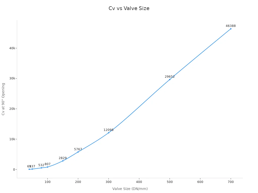
Bigger valves with more open paths tend to have higher Cv values, allowing for greater flow rates.
To find the needed Cv for a pneumatic valve, use this formula: Cv = Q / (k_flow * sqrt((P_in - P_out) * (P_in P_out))). Here, Q is the flow rate in SCFM, k_flow equals 0.6875 for dry air at standard conditions, and P_in and P_out are absolute pressures in psia. This formula comes from the pneumatic valve flow equation and ensures proper valve sizing.
For liquids, the basic Cv equation is Cv = Q * sqrt(SG / ΔP). Compressible air needs extra factors. The ANSI/NFPA T3.21.3 specification defines the test conditions: upstream pressure of 95 psia and a differential of 1 psi. Manufacturers may differ from this standard, so check which standard applies to your valve.
Avoid making your valve too big. A valve that is too large runs at only a small part of its travel, causing hunting and extra wear. Aim to size the valve for operation at 70-90% of travel. An undersized valve causes pressure drop and wear. An oversized valve is inefficient and hard to control.
Think about the flow characteristic too. Linear valves show flow rate changing directly with stem position. Quick-opening valves reach maximum flow at a low percentage of stem range. Equal-percentage valves produce equal percentage changes in flow for equal changes in travel. Globe valves typically have preferred linear characteristics. Non-linear valves may need special disks to get a desired profile.
Pressure and Temperature Ratings
ASME B16.34 defines pressure-temperature ratings by class and material. For a Class 150 WCB (carbon steel) valve, the maximum allowable working pressure is 285 psig (19.6 bar) at 100°F (38°C). This drops to 80 psig (5.5 bar) at 1000°F (538°C). Class 300 WCB is rated 740 psig at 100°F, with the same derating curve.
The standard includes classes 150, 300, 400, 600, 900, 1500, 2500, and 4500. Higher class numbers mean higher pressure-handling ability. The PN rating system gives working pressures from 6 bar to 160 bar at ambient temperature. Hydrostatic shell test pressures run at 1.5 times the rated pressure.
Pressure ratings drop as temperature rises. A valve rated 200 psi cold working pressure only holds within about 20°F to 100°F. Higher temperatures lower the safe working pressure. You must match the valve's pressure and temperature ratings to your system's operating conditions.
Material Selection and Environmental Compatibility
The media you handle and the environment around the valve decide which materials you need. Choose materials that stand up to caustic media or corrosive environments to prevent damage and ensure safe operation.
Body Materials (WCB, CF8, etc.)
|
Material |
Corrosion Resistance Level |
Key Limitations |
|---|---|---|
|
WCB (Carbon Steel) |
Low |
Poor resistance to chlorides, seawater, and sour environments; not suitable for H2S unless qualified. Needs protective coating or corrosion allowance. |
|
CF8M (Cast 316 Stainless Steel) |
Moderate to High |
Prone to pitting/crevice corrosion in warm chloride environments; risk of sulfide stress cracking in sour service. Preferred over 304 for chloride tolerance. |
CF8M is a cast austenitic stainless steel with molybdenum, similar to AISI 316. It offers better resistance to chlorides and chemicals than CF8. For aggressive chloride or seawater service, duplex or higher alloys are recommended.
Both WCB and WCC are carbon steel materials with similar corrosion resistance. They work fine in non-corrosive environments. They need protective coatings, surface treatments, or cathodic protection in corrosive media. Neither material suits seawater, high-chloride, acidic, or alkaline environments without extra protection. For highly corrosive services, use stainless steel grades such as CF8M or specialized alloys instead of WCB/WCC.
Seal and Trim Materials
Seal materials must match your temperature range and chemical compatibility needs.
|
Material |
Temperature Range |
Notes |
|---|---|---|
|
Bellows seal |
Up to 550°C |
Extreme tightness, used in nuclear, toxic, vacuum applications |
|
PTFE |
-200°C to 260°C |
Also used as seat and packing material |
|
PEEK |
-60°C to 260°C |
Mainly used as seat material |
|
FKM (Fluorine Kautschuk) |
-50°C to 232°C |
O-ring material, good chemical properties |
|
FFKM |
-15°C to 325°C |
Premium O-ring, very high temperature resistance |
|
Graphite |
-200°C to 538°C |
Common packing, fire-safe seal |
Viton (FKM) offers excellent resistance to high temperatures. You will find it in chemical processing, oil and gas, and applications handling aggressive fluids.
TANGGONG control valves offer body materials including WCB, WC6, CF8, and CF8M. Trim options include SS304, SS316, and Stellite 6. These choices cover a wide range of industrial applications. The valves handle temperatures from -196°C to 650°C, depending on trim and seat material.
Practical Applications of Flow Control Valves
Flow control valves appear in nearly every automated system you encounter. They manage cylinder speed, regulate conveyor motion, and maintain precise process conditions in industrial plants. Understanding where and how to apply them makes the difference between smooth operation and constant maintenance headaches.
Controlling Pneumatic Cylinder Speed in Automation
In automated assembly lines, you need cylinders that move at predictable speeds. The traditional method uses a needle valve to restrict airflow manually. You adjust the valve until the piston moves at the desired pace. This approach works, but it has limitations. Manual adjustment takes time, and the setting drifts as conditions change.
Modern systems offer better options. Electronic pressure regulators control supply air pressure, which indirectly affects cylinder speed. Mass flow controllers go further. They directly manage the volume of air delivered per unit time, giving you precise velocity control. Combining both approaches delivers stable, repeatable speed control, especially valuable in robotics and precision assembly.
The placement of your flow control valve matters as much as the valve itself. According to Festo's product management expert, you should regulate exhaust air rather than supply air. This method uses full line pressure for actuation. The smaller upstream volume reacts instantly while the larger downstream volume bleeds off slowly, creating a cushioning effect. Restricting incoming pressure causes the downstream side to vent, leading to rapid filling of the small retracted volume and a resulting stick-slip lurching motion. IMI Norgren's product champion summarizes it simply: "When in doubt, meter out. It's a sin to meter in."
For most cylinder applications, control the speed on the exhaust side. The venting chamber continuously exerts counter pressure on the other chamber, which fills with compressed air without restriction. This creates controlled movement and avoids the stick-slip effect.
Regulating Flow in Conveyor and Material Handling Systems
Conveyor systems rely on flow control valves to maintain consistent belt speed and smooth starts. You find these valves in industrial automation controlling robotic arms, conveyor belts, and process systems. Agricultural machinery uses them for precision spraying, seeding, and harvesting equipment. Construction equipment regulates heavy-duty cylinders in excavators or loaders. Water management systems control flow in irrigation, municipal, and wastewater networks.
Cylinders with hydraulic speed regulation, pneumatic devices in automatic sequences, extrusion and molding machines, and any equipment requiring a smooth feed rate all depend on flow control. Without proper regulation, conveyor belts jerk forward, products shift position, and downstream equipment jams.
TANGGONG Control Valves in Process Industries
Process industries demand more than simple speed control. They need continuous modulation of flow, pressure, and temperature under extreme conditions. TANGGONG control valves deliver this precision in petrochemical and power generation plants.
Petrochemical and Power Generation Use Cases
|
Application Area |
Specific Function |
Industry |
|---|---|---|
|
Upstream choke and pressure reduction |
Cage trim shields valve body from high-velocity gas jets, maintains precise flow control, dissipates fluid energy to protect downstream headers |
Petrochemical (Oil & Gas) |
|
Refining process stream throttling |
Stabilizes process streams in distillation columns under changing line pressures, uses durable materials for acid/sour gas handling |
Petrochemical (Refining) |
|
Boiler feedwater throttling |
Handles high pressure drops without trim destruction, solid cage walls prevent cavitation damage, uses suitable sealing rings |
Power Generation |
|
Steam turbine bypass and attemperation |
Dumps excess energy during grid dropouts, anti-cavitation cages pass particulate matter, reduces noise, protects turbine blades |
Power Generation |
|
Severe service corrosive fluid modulation |
Custom trim materials resist chemical attack, e.g., Alloy 20 for sulfuric acid, Stellite facing for high-temperature corrosive applications |
Chemical (also petrochemical) |
|
High-temperature thermal fluid control |
Balanced cage trim maintains continuous process control at peak temperatures, prevents plug binding |
Chemical / Power Generation |
Ensuring Safety and Efficiency in Critical Operations
Each application above demands a flow control valve engineered for its specific challenge. In upstream choke service, the cage trim protects the valve body from high-velocity gas jets. In boiler feedwater service, solid cage walls prevent cavitation damage. In steam turbine bypass, anti-cavitation cages reduce noise and protect turbine blades.
These valves operate continuously, responding to control signals from sensors and controllers. They maintain stable process conditions that keep plants running safely and efficiently. A failure in any of these applications can shut down an entire facility or create dangerous conditions. That is why TANGGONG control valves undergo rigorous testing and certification before shipment.
Installation and Adjustment Best Practices
Getting the valve on the machine is only half the job. You need to mount it correctly, tune it properly, and avoid common mistakes. Each step affects how well your system performs and how long the valve lasts.
Proper Mounting and Orientation
Start with a clean workspace. Dirt and debris cause more valve failures than any other factor. Cap all ports until you connect them. Keep the area free of obstructions that could interfere with the installation.
Follow the flow direction arrow on the valve body. Installing the valve backwards causes performance issues or complete system failure. The arrow shows you which way the fluid should travel. Position the actuator so you can reach it easily for adjustments and maintenance.
Support the valve properly. Use brackets and supports to prevent stress on the valve body and piping. A heavy valve hanging on unsupported pipe creates strain. That strain leads to leaks and premature wear. Securely mount any attached equipment, such as positioners or feedback devices.
Seal all connections correctly. Use the right gaskets and O-rings for your application. Follow the recommended torque specifications for flanged connections. For threaded connections, apply thread sealant as needed. Avoid over-tightening, which damages threads and distorts the valve body.
Consider the piping design around the valve. Use expansion joints where thermal expansion could stress the system. Keep the valve away from sharp bends that cause turbulence. Install isolation valves upstream and downstream. This lets you service the control valve without draining the entire system.
Mounting orientation rule: Flow control valves should be installed as close as possible to the actuator port. The governing principle is: "When in doubt, meter out. It's a sin to meter in." Mounting on the compressed air side (metering in) causes erratic, jerky actuator motion due to pressure fluctuations; therefore, the correct orientation is to mount directly on the actuator ports with the flow control set to meter out (exhaust).
After mounting, calibrate the control system. Configure the actuator, feedback devices, and control algorithms. Then run a full system test. Check for leaks, correct positioning, and proper response to control signals. Document everything—calibration settings, modifications, and maintenance requirements. Good records save hours of troubleshooting later.
Tuning the Valve for Desired Performance
Adjusting a flow control valve takes patience. You want incremental changes, not big swings. The process follows a simple loop: adjust, test, observe, refine.
-
Prepare the system: Shut down the system safely. Identify the target flow rate from your specifications. Check the valve's current position. Install flow meters and pressure gauges so you can measure what the valve actually does.
-
Establish a baseline: Bring the hydraulic or pneumatic system to normal operating temperature. Cycle the circuit and observe the current state. If you have a new valve, start from a known position—usually fully closed or fully open, depending on the design.
-
Make the initial adjustment: Turn the adjustment screw slowly. Clockwise reduces flow. Counterclockwise increases flow. Make only 1/8 to 1/4 turns at a time. Test after each adjustment. For pressure-compensated valves, set the target flow rate directly. For lever-operated valves, move the lever to a new position.
-
Observe and measure: Cycle the system and note changes in actuator speed, flow rate, and system sounds. Compare the flow meter reading to your target. Allow the system to stabilize for a minute after each adjustment before judging the result.
-
Iterate and refine: Compare the new performance to the target. Repeat the adjustment and observation steps until you hit the desired speed. Small tweaks work better than large turns. Each adjustment builds on the last one.
-
Secure the setting: Tighten the locknut carefully to preserve the setting. Use locknuts or clips to prevent vibration from changing the adjustment. A loose setting drifts over time.
-
Verify under working conditions: Test the system under various loads and conditions. Inspect for leaks. Monitor temperature. Listen for abnormal noises. Document the initial valve position, final flow rate, system pressure, date, and observations. This record helps you calibrate future valves and diagnose problems.
The key is patience. Each 1/8 turn changes the flow a little. Rushing the process leads to overshooting the target and chasing the setting back and forth.
Common Mistakes to Avoid
Even experienced technicians make errors. Knowing the common pitfalls helps you avoid them.
Incorrect Sizing and Valve Type Selection
Choosing the wrong valve size causes more problems than any other mistake. An oversized valve operates at only a small part of its travel. This causes hunting and extra wear. The valve constantly overshoots and corrects, never settling into a stable position. An undersized valve creates excessive pressure drop. It cannot deliver the flow your system needs.
Match the valve's Cv to your actual flow requirements. Use the sizing formulas we covered earlier. For pneumatic systems, calculate Cv using the flow rate, inlet pressure, and outlet pressure. For liquids, use the specific gravity and pressure differential. When in doubt, consult the manufacturer's sizing service. TANGGONG offers free valve sizing consultations based on IEC 60534 standards.
Also match the valve type to the task. A simple needle valve works for manual speed control. A flow control valve with a check valve handles one-way speed regulation. A full control valve with an actuator serves continuous process modulation. Using the wrong type means the valve cannot perform its intended function.
Ignoring Manufacturer Guidelines
Manufacturers provide installation and maintenance instructions for a reason. Ignoring them leads to failures. The most common violation is incorrect orientation. Installing the valve backwards, ignoring the flow direction arrow, causes performance issues or complete system failure.
Contamination is another frequent problem. Failing to cap ports and keep the system clean during installation introduces dirt and debris. That contamination leads to valve sticking, erratic speed, and other problems. A single grain of sand can score a valve seat and ruin the seal.
Other guidelines matter too. Torque specifications exist to prevent both leaks and thread damage. Temperature and pressure ratings define safe operating limits. Material compatibility determines whether the valve survives contact with your media. Follow the manufacturer's recommendations for sealing materials, mounting orientation, and maintenance intervals.
The best valve in the world fails when installed incorrectly. Take the time to read the manual, follow the specifications, and document your work. The few extra minutes save hours of troubleshooting later.
Proper installation and adjustment transform a good valve into a reliable system component. Clean work, correct orientation, and patient tuning deliver smooth, predictable actuator motion. Avoiding common mistakes keeps your system running and your maintenance costs low.
A flow control valve manages fluid speed and motion in pneumatic and hydraulic systems. You now understand its core mechanism: a variable orifice that adjusts flow. You also know the main types, from simple needle valves to advanced control valves.
Proper selection, installation, and adjustment deliver real benefits:
-
Better product quality through reduced process variability
-
Higher efficiency with less waste and lower energy consumption
-
Minimized downtime from early problem detection
-
Optimized system performance through condition monitoring
These advantages improve your bottom line and extend equipment life. Apply this knowledge to your next project. For complex applications requiring precise process control, consult the experts at TANGGONG VALVE. They offer free sizing consultations and decades of industrial experience.
FAQ
What is the difference between a control valve and a shut-off valve?
A control valve adjusts flow to keep a process variable at the right level. It works with 4–20 mA or digital signals. A shut-off valve only opens or closes fully. It seals tightly when closed. Pick based on whether you need fine adjustments or just start and stop.
Should I use meter-in or meter-out control?
Use meter-out control for pneumatic cylinders. It limits the air leaving and builds back-pressure. This cushions the piston and stops jerky moves. Meter-in control limits the air coming in. Air compresses and then expands fast, causing sudden jumps. The simple rule is: when unsure, meter out.
What is the difference between pneumatic and electric control valves?
Pneumatic control valves use compressed air to move their actuators. They react quickly and can fail safely. They work well in dangerous areas. Electric control valves use motor-driven actuators. They give exact positioning and fit remote sites without air. Your plant's setup often decides which one to use.
What is cage-guided trim in control valves?
Cage-guided trim uses a round cage with precise openings. The cage guides the plug and shapes how flow behaves. It lowers noise and stops cavitation. It also boosts capacity and makes trim last longer. This design handles high pressure and high heat well.
How do I size a flow control valve for my application?
You need fluid properties, flow rate range, inlet and outlet pressures, temperature, and allowed pressure drop. For pneumatic valves, use the formula Cv = Q / (k_flow * sqrt((P_in - P_out) * (P_in P_out))). TANGGONG gives free valve sizing help based on IEC 60534 standards.
What certifications should I look for in a control valve?
Look for ISO 9001:2015 certification and CE marking. Check that the valve meets ANSI/FCI 70-2 shutoff standards. TANGGONG control valves also meet SGS certification. SIL-capable designs are available on request. Third-party checks by TUV, SGS, or DNV are also possible.
Why does my pneumatic cylinder move erratically?
You likely use meter-in control instead of meter-out. Limiting supply air causes pressure drops and jerky motion. Air compresses, then expands suddenly. This creates stick-slip behavior. Switch to meter-out control. Mount the flow control valve right on the actuator port. This builds back-pressure and smooths the movement.