



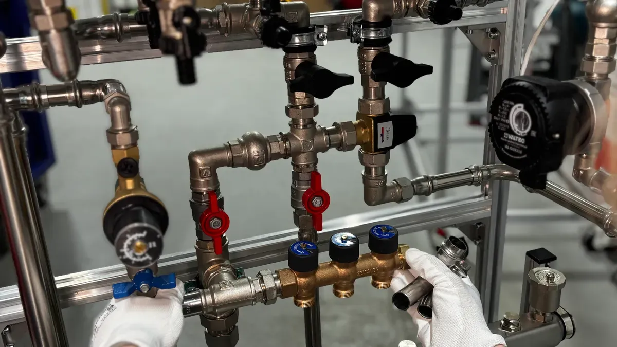
A temperature control valve is an automatic valve that controls liquid flow to keep a set temperature. You need this mechanical tool to guard important factory equipment from getting too hot.
Temperature control regulators keep system liquids steady by managing heating liquid flow. Self-moving units use expanding materials, while powered units use outside signals.
High-performance butterfly units cut cooling pump power use by 30% in factory systems. You can learn the temperature control valve working principle to boost total plant output. Correct setup stops bad heat changes and sudden work shutdowns. This device shifts internal liquid paths constantly to guarantee exact heat balance throughout your system cycle.
Key Takeaways
-
Temperature control valves keep system liquids at a steady heat level.
-
Sensors constantly measure liquid temperature to make the valve stem move.
-
Self-operated valves use expanding wax or liquid to work without any extra electricity.
-
Powered valves use air or electricity to manage the fluid flow very accurately.
-
Three-way mixing valves combine two incoming liquid flows into a single outgoing flow.
-
Three-way diverting valves divide one entering liquid flow into two exiting paths.
-
Correctly choosing valve sizes protects factory gear and lowers energy use a lot.
Temperature Control Valve Working Principle and System Overview
You keep process fluid stable by controlling heat energy flow through factory pipes. The simple temperature control valve working principle uses liquid movement, sensor signals, and mechanical control. Steady flow adjustments keep the process fluid steady during changing work conditions. Choosing the right temperature control valve ensures long-term process reliability for all factory heating and cooling systems. Adding a high-performance temperature control valve protects plant tools from heat changes and hot damage.
The Thermal Control Feedback Loop
A thermal feedback loop works in a continuous closed loop sequence. This automatic system changes process settings constantly through four main functional steps.
|
Sequence Stage |
System Action |
Process Outcome |
|---|---|---|
|
Thermal Sensing |
Sensor measures fluid conditions |
Detects heat deviation |
|
Signal Reaction |
Controller evaluates sensor output |
Generates correction command |
|
Stem Actuation |
Actuator applies mechanical force |
Repositions internal plug |
|
Flow Modulation |
Valve regulates fluid volume |
Restores target setpoint |
Thermal Sensing Phase
You start this working process at the temperature sensor placed right inside the liquid stream. A main transmitter or filled bulb checks liquid heat changes continuously. Filled tubes or solid wax parts grow or shrink as heat changes inside the pipe. This physical growth creates matching mechanical force inside the sensor space. Precise RTD probes can also read heat levels to create electric signals. The sensor then sends this quick signal forward to start needed automatic fixes.
Signal Controller Reaction
The controller gets the sensor signal right away from your main checking unit. It checks this actual read number against your set goal right off the bat. The inside chip finds the exact difference and plans the right fixing action. An electronic signal check triggers the control box output. The controller changes this heat difference into a standard air or electric output signal. It pushes this command to the main actuator to bring back heat balance.
Valve Stem Actuation
The actuator changes coming signals into direct physical push force. Air pressure lines or electric motors move the valve stem up or down smoothly. This exact stem movement shifts the inside plug position next to the seat. A open valve begins closing as heat rises in factory heating systems. This straight movement changes the open path space inside the valve body. So, this mechanical movement changes your hot fluid or cold water flow speed directly.
Operational Mechanics and Fluid Physics
Knowing fluid movement rules lets you improve total system response time. You must balance machine settings with heat movement speeds to get steady process control.
Setpoint and Deadband Adjustment
You set up work limits by picking the right goal heat on your main controller. This target heat marks your exact wanted thermal point for the process fluid. You must also set a correct quiet space to stop fast valve stem movement. This quiet zone creates a small non-moving area around your set target heat. This small gap keeps the actuator from moving constantly for tiny signal changes. Setting this quiet zone right protects internal seat parts from extra wear to add useful working years.
Flow Coefficient and Response Time
You find the flow capacity to size your valve body correctly for your pipe setup. Designers use IEC 60534 size rules to pick needed fluid flow limits for high load work. The flow rating shows the liquid volume moving through the valve body at one pressure drop. System delay makes a natural time lag between stem movement and heat control in the loop. You must match the actuator action speed with this natural system delay. Quick actuator movement stops fast heat jumps in busy factory lines. Correct sizing gives smooth continuous flow control under changing plant operating loads.
You can learn the temperature control valve working steps by studying these main parts. Every temperature control valve needs exact matching between machine moving forces and liquid heat movement rules. Knowing this temperature control valve working principle helps you improve overall plant safety. Good heat control increases total working output through every production run in your plant.
Temperature Control Valve Diagram and Component Anatomy
System Diagram Interpretation
Flow Path and Port Identification
You read factory blueprints by tracking common pipe paths and basic symbols. Standard rules like ISA 5.1 and ISO 10628 mark these drawings clearly. You can spot a temperature control valve easily by finding its tag code, like TCV-101. The drawing labels three-way valve ports with letters A, B, and AB. Port AB works as the shared port, while ports A and B change the liquid direction.
You trace liquid paths to check if your unit mixes or splits the stream. Mixing setups combine two inlet flows from ports A and B into one outlet at port AB. Diverting units take one incoming stream from port AB and push it into two separate outlets.
Feedback Loop Diagram Mapping
You map the whole loop by following four simple steps on your drawing chart. First, a tiny sensor reads the hot liquid moving inside the pipe. Second, a calculator compares this read number with your target goal to spot any difference. Third, the system controller turns this difference into a direct action order.
Solid lines on your chart mean electric signal wires, while dashed lines show air tubes running to the driver.
Fourth, this signal moves the drive unit to shift the valve stem smoothly. This exact physical movement adjusts your liquid flow to bring back correct heat levels.
Core Structural Components
Sensing Element and RTD Probes
You depend on accurate main parts for reliable heat control across your system pipes. Smart RTD probes check liquid heat constantly to send quick electric signals back to your control box. Some self-moving units use wax parts or filled tubes that grow naturally when heat rises.
Actuator and Bonnet Assembly
You change liquid flows by placing an electric motor or air drive onto the top bonnet frame. TANGGONG control valve units use strong bolted bonnets to lock internal parts safely under high pressure. The drive pushes the stem through the top packing to move inside parts smoothly.
Valve Body and Internal Trim
You guard your system across wide heat ranges from -196°C to 650°C using strong body parts. TANGGONG builds tough valve bodies from ASTM A351 CF8 stainless steel to handle hard work. The inside trim uses 410 stainless steel parts with hard Stellite coating on the disc and seat. TANGGONG control valve designs use cage-guided trim to keep noise low and block damaging air bubbles. This balanced cage creates slow flow paths and multi-step pressure drops to cut shaking. This smart build improves total working principle output while controlling heat continuously.
Key Types for Industrial Temperature Control
You choose control devices based on power options, exact needs, and system setup complexity. Self-running heat units work without any outside power. Outside powered control options offer high accuracy across large factory process systems.
|
Feature |
Self-Operated Thermostatic Valve |
Externally Actuated Valve |
|---|---|---|
|
Power Source |
Internal process fluid energy |
Compressed air or electricity |
|
Precision |
Basic temperature control |
High precision positioning |
|
Response Speed |
Slower heat reaction |
Fast stem movement |
|
Setup Cost |
Lower installation expense |
Higher system investment |
Thermostatic Self-Operated Valves
Self-moving heat tools offer direct internal control right inside your liquid pipe. You do not need outside wires or compressed air tubes for basic heat control.
Plant workers set this working level during early factory build time. Changing this heat target means placing a new inside heat part inside the valve unit.
Thermostatic Wax Element Operation
You count on a heat phase switch inside the sealed wax part to make physical movement. Expanding wax pushes right against an inner wall and piston when temperatures shift.
|
Thermal State |
Wax Element Behavior |
Effect on Valve |
|---|---|---|
|
Cold (wax solid) |
Paraffin wax contracts; return spring retracts piston |
Direct valve opens; reverse valve closes |
|
Hot (wax liquid) |
Wax expands during phase change; pushes piston |
Direct valve closes; reverse valve opens |
This solid to liquid growth gives matching stem motion across a small heat range. The mechanical push controls fluid flow without outside units, keeping good working states in simple loops.
Capillary Tube Liquid Expansion
Liquid growth systems use a far-off sensor bulb attached through a thin metal tube. Heat growth of the liquid center creates fluid pressure inside the driver bellows.
This liquid pressure pushes the inner valve stem to move smoothly against a tuned spring. You place the far-off bulb directly inside the main stream while setting the main body nearby.
TANGGONG Control Valve Actuation Options
You get exact process control by using TANGGONG valve units built for tough factory work. These powered units get electric commands to control liquid paths smoothly.
Modern factory plants link these automatic valves right into main control networks. You get ongoing health updates, fast heat target changes, and safe system control.
Pneumatic Diaphragm and Piston Actuators
Air diaphragm setups use a balanced force method between air push and spring power. A smart air unit converts a 4–20 mA signal into a 3–15 psi or 6–30 psi air push.
Air piston drives supply much stronger push forces for big valve sizes and high pressure drops. These air drivers can move faster than 1 second per 10 inches of travel to guard plant tools.
Electric Motorized Control Valves
Electric motor drives use smart gear sets to place the valve stem without air pressure. Inside sensors deliver exact placement accuracy within ±0.5% for ongoing heat control.
These smart electric drives work with top digital systems like HART, Modbus RTU, Modbus TCP, and Profibus. You track live force levels, motor power, and stem location right on your screen setup.
3-Way Temperature Control Valve Operation: Mixing vs. Diverting
You use a three-way valve to manage fluid paths in industrial liquid heating and cooling circuits. This reliable control device directs liquid streams based on real-time system process conditions. You can select either a mixing configuration or a diverting configuration to handle thermal fluid loops. Both structural designs share similar outer body profiles, but their internal trim patterns and fluid flow directions differ completely.
3-Way Mixing Valve Dynamics
Dual Inlet to Single Outlet Configuration
A three-way mixing temperature control valve combines two separate incoming fluid streams into one single outlet stream. You connect the hot fluid supply pipe to one inlet port and the cold fluid supply pipe to the second inlet port. The blended liquid exits through the common discharge port. You must verify essential installation parameters before placing a mixing unit into your pipe network:
-
Define the flow logic first by identifying which two ports serve as fluid inlets and which port serves as the single mixed outlet.
-
Verify the pressure rating, temperature limits, and body material compatibility of your equipment before starting system operation.
-
Check pressure drop differences between the two inlet ports to prevent operational failures and reverse fluid backflow.
-
Avoid confusing the mixing fluid path with a diverting fluid path or using the valve as a simple two-way shutoff unit.
A characterized T-port passage allows the internal trim to adjust the blend ratio smoothly while reducing internal pressure drop and fluid turbulence.
Thermal Blending and Proportional Control
You achieve precise thermal blending when the internal plug modulates both inlet openings at the same time. The actuator receives continuous temperature feedback from a sensor or system controller. It moves the valve plug continuously rather than cycling on and off repeatedly. If the mixed liquid temperature rises above your setpoint, the controller closes the hot port and opens the cold port proportionally. It reverses this physical action when the process liquid temperature falls below setpoint.
-
The valve continuously modulates between hot and cold inlet feeds to adjust the liquid flow ratio.
-
Total flow volume through the outlet port remains nearly constant during stem adjustment.
-
Equal-percentage trim profiles maintain stable process control gain across varying flow splits.
-
Tight proportional temperature control cuts system energy use by 10–20% compared to manual adjustments.
This steady proportional control protects upstream pumps from sudden pressure changes and supports efficient temperature control across the plant.
3-Way Diverting Valve Dynamics
Single Inlet to Dual Outlet Configuration
A three-way diverting temperature control valve receives a single incoming fluid stream and splits it between two separate outlet paths. You install this control device when your process requires fluid redirection for temperature control rather than thermal fluid blending.
|
Port / Element |
Function |
Bypass-loop thermal management role |
|---|---|---|
|
AB |
Single inlet port |
Receives the single incoming fluid stream from the supply pipe |
|
A |
Outlet port |
Directs fluid flow toward the heat exchanger or process coil |
|
B |
Outlet port |
Directs fluid flow straight to the bypass return line |
|
Valve action |
Modulates flow split |
Shifts fluid between the coil and bypass leg to maintain temperature |
The internal stem repositions the plug against opposing seat rings to adjust fluid distribution between the two outlets. Continuous working adjustments keep total upstream pipeline pressure stable during heavy operational load shifts.
Bypass Loop Thermal Management
You rely on bypass loop thermal management to protect sensitive process machinery during cold start periods. Self-actuated diverting valves often use internal wax cartridges to sense fluid temperature directly without external sensors or complex controller loops.
-
During cold starts, the internal element routes cold fluid through the bypass line to shorten equipment warm-up times.
-
Fluid redirection through the bypass loop lowers return-line backpressure during initial system startup.
-
When liquid heat reaches the setpoint, the valve diverts flow toward the main cooler unit or heat exchanger.
-
Stable fluid management protects lubricant viscosity, prevents pump cavitation, extends pump service life, and lessens component wear.
This simple mechanical working principle ensures reliable thermal performance for heavy engine jackets and industrial process machinery. Proper diverting setups match cooling capacity directly to changing thermal load requirements.
Industrial Applications and Thermal Control Schemes
Heat Exchanger Thermal Control
Steam Heat Exchanger Control Loops
You put a temperature control valve on a steam line to manage heat in a shell-and-tube heat exchanger. The sensor checks liquid heat at the outlet. Then, the automatic valve changes steam flow to match process needs. TANGGONG VALVE makes these units in sizes from DN15 to DN600.
High-pressure steam systems need strong materials that stop leaks completely. You can pick cast carbon steel WCB or stainless steel CF8M for the valve body. These parts use Stellite 6 trim to stop steam damage. Every valve passes API 598 seat tests to guarantee top quality. The valve design meets ANSI/FCI 70-2 rules for great leak safety.
Plate Heat Exchanger Bypass Systems
Plate heat exchangers use fluid bypass loops to keep heat steady during fast work changes. You place a control valve on the bypass pipe to move extra liquid away. This action stops sudden heat damage across thin steel or titanium plates. It keeps liquid heat steady without stopping main fluid movement.
Correct valve sizing gives you the best flow split between your heater and bypass lines. You can pick pressure ratings from Class 150 to Class 2500 for tough factory pipes. TANGGONG VALVE builds these parts under strict ISO 9001:2015 quality rules. Precise stem movement saves energy and makes tools last longer.
Heavy Engine and Process Cooling
Jacket Water Thermal Regulation
Big factory diesel engines use jacket water cooling systems to stop dangerous heat damage. A three-way temperature control valve sends hot fluid to the radiator or back to the engine. The whole system keeps optimal engine heat during changing work loads.
Sending cold fluid through the bypass line helps the engine warm up faster during cold starts. When fluid heat hits the set point, the driver pushes the plug toward the cooler. This continuous temperature control guards engine blocks against heat stress and deep cracks.
Lubricating Oil Thermal Protection
Heavy machines need exact oil heat control to keep the lubricant thick and strong. You can use three-way diverting valves to direct oil through outside heat exchangers. The valve moves cold oil past the cooler when a machine first starts up.
As friction creates heat, the valve moves to send warm oil into the main oil loop. Keeping heat steady stops bad bearing wear and lowers total repair costs. Factory workers get safe heat control for heavy power plants and oil refiners.
You improve heat efficiency, process stability, and overall system safety when you choose the correct temperature control valve. Self-moving heat units need no outside electrical power, allowing them to work safely inside dangerous factory locations. High-precision powered control units follow air or electric signals to shift the valve stem quickly, which stops wasted energy and avoids constant process problems. TANGGONG VALVE builds strong industrial valve designs that meet strict certified ISO 9001:2015, CE, and SGS quality rules. You get exact working performance alongside steady fluid heat management across every factory loop. Reach out to our technical team today to receive your free IEC 60534 control valve sizing meeting.
FAQ
What is the difference between a control valve and an isolation valve?
A control valve shifts fluid flow continuously to balance process levels. An isolation valve only opens or shuts fully to stop fluid movement.
How does a self-operated unit work without power?
Inside wax parts expand when liquid heat rises. This physical growth pushes the stem directly to shift the plug without outside power.
What is the temperature control valve working principle?
The temperature control valve working principle relies on a feedback loop. A sensor reads fluid heat, a controller checks the signal, and an actuator shifts the stem to adjust liquid flow.
What are the main benefits of cage-guided trim?
Cage-guided trim guides the plug inside smooth cut openings. This design lowers noise, stops gas bubbles, and guards inside parts against heavy pressure drops.
How do you choose between 3-way mixing and diverting configurations?
You pick a mixing unit to join two incoming liquid streams into one outlet. You select a diverting unit to divide one fluid path into two separate outlets.
How do you size hardware for precise system operation?
You find flow capacity using fluid traits, flow speed ranges, pressure drops, and heat. TANGGONG offers free math checks using IEC 60534 rules to ensure exact process control.