



You improve heating and cooling systems using a three way control valve to change fluid flow. Knowing how the 3-way valve works helps you balance temperatures in your equipment. This 3-way valve has three openings labeled A, B, and AB. In mixing uses, liquids enter openings A and B, mix inside the valve body, and leave through opening AB. Modern mixing valves keep output temperatures very exact. In diverting uses, liquid enters opening AB and splits into openings A and B. Fast-acting diverting valves help protect your machinery. You can trust TANGGONG VALVE from Wenzhou, China for accurate 3-way control solutions that meet official IEC 60534 and ANSI/FCI 70-2 standards. You learn how the 3-way valve works to control fluid flow easily.
Key Takeaways
-
Three-way control valves direct the flow of liquids to keep temperatures steady in heating and cooling systems.
-
Mixing valves blend two incoming liquid streams into a single outgoing stream.
-
Diverting valves split one main incoming liquid flow into two separate exit paths.
-
Smooth movement of inner valve parts keeps the total liquid flow steady inside the pipes.
-
Picking the right valve size stops harmful noise, shaking, and inside damage.
-
Automatic motor drivers precisely move the internal valve stem to maintain a steady temperature.
-
TANGGONG VALVE offers reliable control solutions meeting official international standards.
Fundamentals of the Three Way Control Valve
Core Components and Internal Trim
Stem and Plug Geometries
You control liquid motion in a piping system by using a three way control valve. Tough outer shells like WCB carbon steel, CF8 stainless steel, and CF8M stainless steel shield internal parts. Durable Stellite 6 trim components stop internal wear inside cage-guided globe valve setups. The central rod drives a plug to shift liquid movement.
|
Design Principle |
Description |
|---|---|
|
Body Design |
Strong body featuring three ports handles extreme fluid pressures. |
|
Internal Trim Design |
Guided internal trim directs movement and blocks sudden pressure shocks. |
|
Mixing Operation |
Blends two incoming liquid lines into one managed exit route. |
|
Diverting Operation |
Divides one main incoming line into two separate exit routes. |
You master the general 3-way valve working principle by watching internal plug movements. A linear plug shape allows your valve to keep smooth motion through changing temperatures inside a 3-way body.
Linear and Rotary Actuation Options
You choose actuators for an automated flow control valve to achieve top system power. Air-powered diaphragm drivers, air-powered piston drives, and electric motor drivers move the inner rod accurately.
-
Air-powered diaphragm drivers supply quick reactions for steady system adjustment.
-
Air-powered piston drives produce great force for heavy-duty industrial settings.
-
Electric motor drivers offer exact location control for fully automated systems.
These driver choices handle valve pressure levels from Class 150 up to Class 2500 (PN10-PN420). TANGGONG VALVE builds every automated flow control valve to boost total plant safety. Proper rod placement improves performance.
Port Configurations and Flow Paths
Ports A and B Primary Channels
You direct liquids across internal channels to modify your setup. The basic 3-way valve working principle depends on separate liquid paths:
-
For mixing: channels A and B act as inlets, while channel AB acts as the outlet.
-
For diverting: channel AB acts as the inlet, guiding fluid toward channel A or B.
This twin inlet layout permits mixing systems to combine fluid lines smoothly throughout your 3-way setup.
Port AB Common Header Integration
Port AB acts as the main shared header across every liquid network. During mixing, liquids come through ports A and B, then leave out port AB. During diverting, liquid enters port AB, then splits toward ports A and B. A T-shaped 3-way layout aids combining and splitting. An L-shaped 3-way layout shifts flow paths for diverting jobs. You use this 3-way valve working principle to simplify pipe layouts.
Force Balance and Dynamic Pressure
Differential Pressure Across Valve Trim
Fast fluid speed builds strong forces pushing against the valve plug. Learning the 3-way valve working principle assists you in managing pressure changes across internal trim. Liquid pressure drops as fluids squeeze through tight trim openings. Balanced inner cage setups lessen trim stress while lowering fluid turbulence.
Actuator Sizing for High-Drop Service
Large pressure drops require correct actuator sizes to maintain steady flow control. Pressure differences cause unstable pushing forces inside a three way control valve. Powerful drive units stop rod movement inside 3-way control valves. You defend your liquid network by matching actuator drive power to actual pressure needs.
Hydrodynamics of 3-Way Control Valves in Mixing Applications
Mechanics of Mixing Valves
Dual Inlet Flow Combination Dynamics
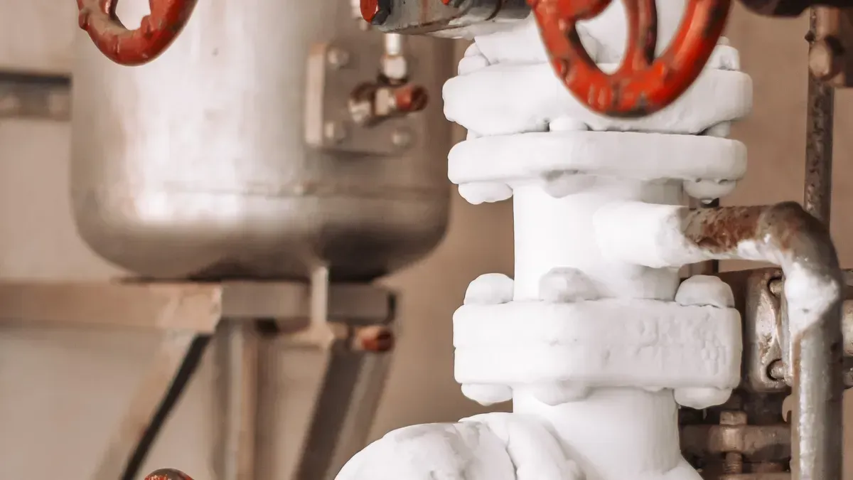
You change how liquids act when two different incoming streams join into one outgoing path. You put in 3-way control valves to handle these joining lines safely. The inner plug shifts constantly back and forth between port A and port B. Liquids pass through both side openings at the exact same time. These two fluid currents meet right inside the main central valve chamber. You count on this setup for tough factory jobs. The shifting plug uncovers one inlet path while shutting off the opposite side port. This synced movement provides managed mixing for your heat process lines. Active liquid forces push hard on the inner plug face while running. You keep system performance steady when water forces stay balanced inside your main mixing setup valve.
Fluid Velocity and Blending Behavior
Liquid speeds up quickly as fluid streams travel through tight inner valve paths. Higher liquid speed creates strong local shaking right next to the plug zone. This fast movement blends hot and cold liquid molecules together completely. You get total liquid mixing before the fluid flows into the main exit pipe. The smooth inner design keeps quiet liquid pockets from forming along port walls. Correct internal sizing guards your downstream pipes against harmful heat shocks. A standard 3-way setup provides steady liquid motion across all working flow speeds. You rely on a tough fluid mixing valve to keep strong mechanical performance.
Thermal Modulation in Thermal Systems
Proportional Hot and Cold Water Control
You tune process temperatures accurately by fitting mixing valves across your building loops. The physical plug spot changes water volume ratios automatically. The inner trim reacts to heat shifts by adjusting liquid paths. You set up sturdy mixing valves to keep process loops steady. These mixing valves shut the cold side port fully at 5°F below your set temperature. They also close the hot side port completely at 5°F above your set point. This physical action gives dependable ongoing performance to control water heat. You boost total system energy savings by keeping tight liquid proportion limits.
Sensor Feedback and Loop Response
Sensors check downstream liquid conditions and send electronic signals back to your actuator. The automatic controller reads these live signals to move the plug spot right away. You see the usual 3-way valve working method inside this ongoing feedback loop. Fast actuator reactions block sudden heat spikes in your sensitive machinery. The inner valve rod glides smoothly to balance out outside temperature changes. This active control loop improves overall system heating results across your plant operations. You shield expensive heating tools by keeping predictable liquid flow exit temperatures.
Pressure Drop in Mixing Modes
Controlling Cavitation and Flashing
You shield inner metal parts by managing local pressure drops across your valve setup. Valve cavitation begins when local liquid pressure falls below vapor pressure levels. Vapor bubbles pop up instantly and burst wildly near the bottom plug of a 3-way globe unit. Bubble bursts cause heavy shaking, loud noise, and metal pitting over time. You use valve diversion by splitting fluid flow through smaller inner paths to shrink vapor bubble sizes. Stepping down pressure drop with several control points in a row also stops inner damage. You position your 3-way unit at higher entry pressure or lower fluid heat points to cut cavitation risks.
Maintaining Constant Total Discharge Flow
You guard downstream pump tools by balancing inner port openings correctly. The inner plug uncovers port A while shutting port B at the same exact speed. This equal movement keeps a steady total flow out through shared port AB. You depend on this predictable setup inside closed circulating water loops. The balanced inner 3-way path holds steady pump pressure across all working modes. You learn the basic 3-way valve working method to stop severe water hammer inside your pipes. Your main fluid mixing system valve promises solid flow stability across all ongoing work.
Operation of Diverting Valves in Bypass Loops
Fluid Splitting in Diverting Valves
Single Inlet to Dual Outlet Paths
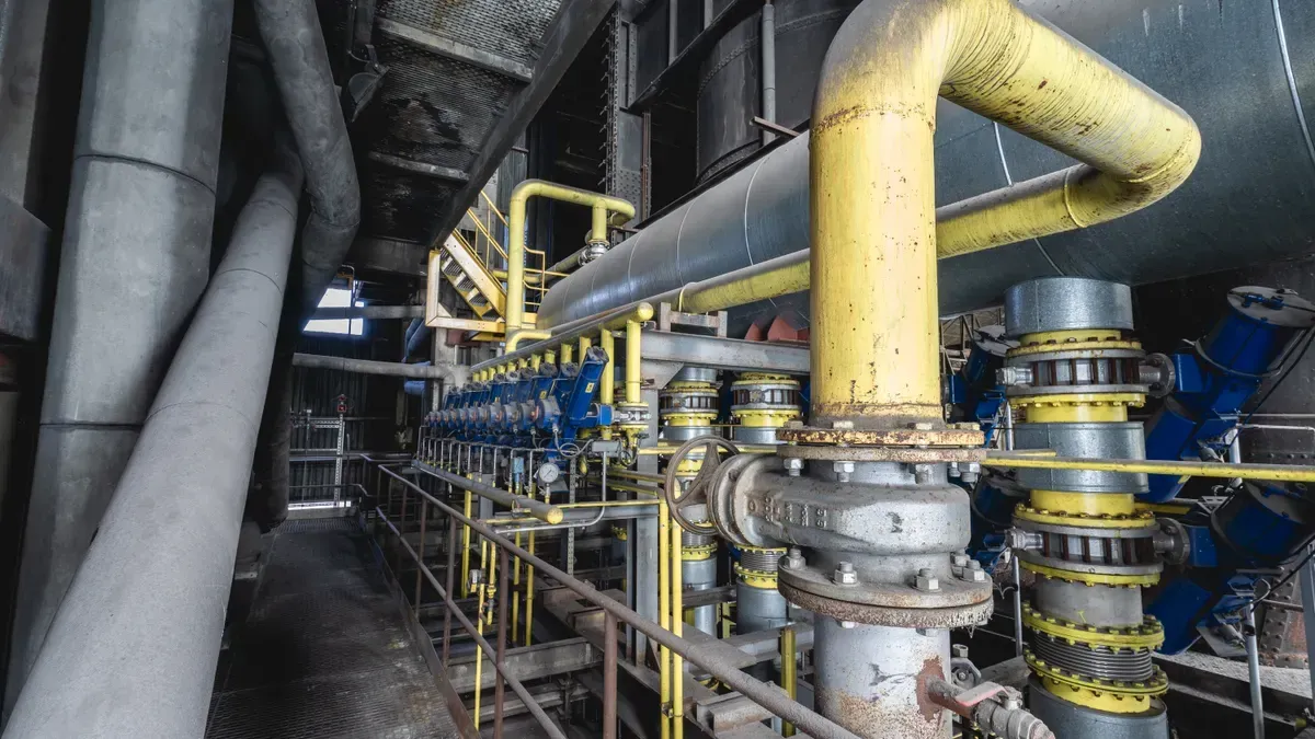
You send fluid into a single entrance port when operating a flow diversion valve. The fluid enters common header port AB. Inside the body, the fluid splits into two distinct paths through port A and port B. This physical setup allows liquid to move toward different process loops based on system demands. You control the internal stem position to change how much liquid goes to each exit. Opening port A closes port B by an equal amount. This opposite movement manages safe fluid routing throughout your piping network.
Unbalanced Forces on Valve Plugs
You face physical dynamic forces when fluid flows into port AB and exits through two ports. Diverting valves experience unbalancing forces pushing directly against the valve plug faces. The fluid pressure enters under the inner plug seats and pushes the stem outward. This fluid force creates dynamic instability during rapid movements. You can apply the basic 3-way valve working principle to predict these plug pushing forces. Selecting strong actuators helps you keep the valve stem completely stable during heavy pressure surges.
Heat Exchanger Bypass Application
Chilled and Hot Water Bypass Loops
You install diverting valves on the supply side before the HVAC heat exchanger coil. A 3-way flow diversion valve splits incoming liquid between the active heating unit and the bypass line. Changing the internal configuration allows the system to direct fluid smoothly around the coil during partial load conditions. You preserve energy efficiency by matching thermal output to live room demand.
|
Factor |
Description |
|---|---|
|
Fluid Type |
Determines material compatibility, temperature, and pressure ratings. |
|
Operating Conditions |
Includes temperature range, maximum operating pressure, differential pressure, and flow rates. |
|
Control Characteristic |
Equal percentage characteristic is preferred for stable coil control across load variations. |
|
Valve Authority |
Should be between 0.5 and 1.0 to avoid distorted installed characteristics. |
|
Leakage Requirements |
Specified by ANSI/FCI standards, where single-seated valves offer tighter shutoff. |
|
Fail-Safe Position |
Moves the inner trim to a safe position upon power or signal loss. |
|
Actuator Type |
Choice between pneumatic or electric based on available utilities, speed, and precision. |
|
Noise Considerations |
Limits exit velocities for high-velocity fluids to reduce operational noise. |
Maintaining Constant System Pump Flow
You place a 3-way valve into the bypass loop to mix inlet and outlet flows. This setup maintains a constant total flow through the heat exchanger regardless of the bypass flow.
-
You eliminate the risk of dead-heading for constant-speed pumps.
-
You avoid additional pressure drop variations so the pump operates at a stable resistance.
-
You achieve faster control response because the valve diverts liquid rather than throttling it.
This constant liquid movement protects your pump from cavitation damage and improves system stability. Using 3-way control valves in constant flow industrial applications protects process hardware.
Trim Selection for Diverting Service
Anti-Cavitation Cage-Guided Designs
You reduce high fluid speeds by choosing specialized anti-cavitation cage trim for heavy industrial applications. Fast liquid velocity drops local pressures and creates damaging vapor bubbles inside standard valve channels. Modern 3-way cage-guided trim divides main liquid paths into many smaller streams. This internal flow diversion valve configuration boosts overall plant operational efficiency. You can study the standard 3-way valve working principle to optimize cage hole sizes. Correct port positioning stops inner metal surface erosion and lowers operational noise levels.
ANSI Class IV, V, and VI Shutoff Standards
You verify internal port seal quality by reviewing ANSI/FCI 70-2 shutoff ratings. Higher standard classes require tighter mechanical seating across inner trim faces.
ANSI Class IV allows a maximum seat leakage of 0.01 percent of full open valve capacity, while Class V and Class VI standards require tight shutoff for critical process isolation.
You evaluate seat materials carefully when choosing a 3-way unit for diverting service. Hardened metal seats resist erosion, while soft seats deliver complete leak-tight shutoff performance. Proper trim selection ensures your process system maintains tight control under variable fluid pressure conditions.
Dynamic Performance and 3-Way Flow Characteristics
Linear vs Equal Percentage Trims
Installed Flow Characteristic Profiles
You select specialized internal trims to control how fluid moves through internal channels. A linear trim changes liquid movement at a constant rate relative to stem displacement. An equal percentage trim changes fluid volume by equal increments for each stem movement step. You achieve steady heat transfer inside heat exchangers by pairing equal percentage trims with non-linear thermal loads.
The installed characteristic changes when fluid resistance alters the pressure drop across your piping layout. High fluid friction distorts the theoretical flow profile of your assembly. You prevent sudden temperature spikes by picking internal trim shapes that match your exact heat transfer curve. Correct trim choices protect process stability during rapid load shifts.
Valve Authority in Variable Flow Systems
You calculate valve authority to measure how effectively your assembly manages fluid movement. Valve authority represents the dimensionless ratio of the pressure drop across a fully open valve to the total circuit pressure drop at design flow. High authority between 0.2 and 0.5 ensures stable control across variable loops. Low authority causes system hunting, rapid cycling, and poor temperature regulation.
- High authority (0.2 to 0.5): Ensures stable regulation without temperature oscillations.
- Low authority (below 0.2): Causes dynamic hunting, valve seat wear, and loop instability.
- Pressure Independent Valves: Provide 100% authority by absorbing circuit pressure shifts automatically.
In variable flow applications, changing pipe resistance alters total pressure conditions across your loops. You keep loop response predictable by maintaining adequate valve pressure differential relative to surrounding pipework. Proper sizing ensures reliable control performance under changing load demands.
Flow Direction and Dynamic Stability
Flow-to-Open vs Flow-to-Close Forces
Fluid vectors produce dynamic forces against internal plug surfaces inside a 3-way assembly. A flow-to-open setup pushes the plug away from its seat face. This arrangement provides smooth throttling action and prevents sudden mechanical slamming. You reduce actuator load demands by utilizing this balanced force orientation during high-drop service.
A flow-to-close setup directs fluid forces to push the plug toward its seat face. High pressure drop creates strong pulling forces near the seating point. This action can cause plug chatter, stem vibration, and premature trim damage. You install a sturdy automated flow control valve to overcome these unbalancing forces safely.
Mitigating Water Hammer and Fluid Shear
Fast stem movement can send dangerous shockwaves through closed loop piping setups. You prevent destructive water hammer by slowing actuator travel speeds during directional switches. Smooth plug motion prevents rapid pressure spikes from damaging downstream pipe joints.
High fluid velocity creates shear stresses that cause rapid trim erosion and surface wear. You install cage-guided 3-way control valves to diffuse high energy fluid paths safely. Diffusing fluid velocity through cage ports protects internal metal surfaces and minimizes operational noise.
Sizing via IEC 60534 Calculations
Flow Coefficient Cv and Kv Calculations
You calculate standard flow coefficients to size your 3-way trim correctly. The IEC 60534 standard defines the relationship between volumetric flow rate, pressure drop, and fluid density. You determine the required Kv or Cv value to handle peak demand without creating excessive pressure losses.
You calculate the flow coefficient using
Kv = Q * sqrt(SG / delta_P), whereQis volumetric flow in cubic meters per hour,SGis specific gravity, anddelta_Pis differential pressure in bar.
Accurate flow coefficient sizing prevents premature cavitation and preserves stable pump discharge head. Over-sizing an assembly forces the plug to operate near its seat, which degrades system performance. Proper sizing matching guarantees smooth modulation across the complete operating stroke.
Media Viscosity and Specific Gravity Adjustments
Heavy oils and dense glycol solutions change fluid behavior through internal ports. High viscosity increases fluid friction, which reduces total effective discharge capacity. You apply viscosity correction factors per IEC 60534 guidelines to recalculate your target valve size accurately.
Specific gravity variations alter the differential pressure requirement across your 3-way valve setup. Dense fluids require higher seat forces and larger port areas to maintain target throughput. You verify media properties to ensure consistent 3-way control performance across all thermal operating conditions.
System Integration with TANGGONG Control Valves
You integrate TANGGONG valve solutions into your plant to achieve improved system efficiency. TANGGONG VALVE operates a 175,000 m² manufacturing facility in Wenzhou, China. The company holds over 200 national patents. You rely on these precision designs for severe industrial applications.
Technical Selection Parameters
Temperature Range from -196°C to 650°C
You select valve body materials based on live thermal conditions. Standard valve designs handle extreme working environments from -196°C to 650°C. Cold liquid loops require tough stainless steel alloys. High-heat steam loops demand strong carbon steel housings. You maintain steady mechanical performance across every 3-way thermal cycle.
You evaluate thermal expansion across internal valve components during engineering reviews. You can request free IEC 60534-compliant valve sizing consultation services from TANGGONG experts. This sizing service ensures your valve handles severe pressure drops safely.
Matching Media Compatibility and Trim Materials
You match internal valve body and trim materials to your specific 3-way fluid properties. Corrosive liquids require specialized stainless steel or fluorine-lined trims. High-velocity fluid streams require hardened Stellite 6 trim surfaces.
|
Parameter |
Selection Requirement |
|---|---|
|
Port Arrangement |
L-port or T-port configurations for 3-way routing |
|
Duty Type |
Continuous modulating control or discrete on-off switching |
|
Material Compatibility |
Matching body, packing, and seats to chemical limits |
|
Trim Configuration |
Anti-cavitation trim choices for severe fluid flow service |
Proper trim selection prevents inner metal wear inside your 3-way fluid circuit.
Digital Control Signal Compatibility
Integration with 4-20mA and HART Protocols
You connect modern digital positioners to your automated flow control valve. Positioners accept standard 4-20mA analog signals from plant computers. Integrated HART protocols send real-time diagnostic data directly to your main control room. This live communication setup protects your 3-way network against unexpected outages.
Quick digital feedback allows precise stem positioning. You maintain accurate process flow rates through every operational shift.
Fieldbus, Modbus, and Profibus Communications
You link your 3-way unit into complex plant automation systems. Digital positioners support Fieldbus, Modbus, and Profibus communication protocols. You monitor stem position, internal pressure, and air supply status remotely.
These digital 3-way networks streamline plant maintenance schedules. You optimize total system output without stopping active process lines.
Installation and Maintenance Guidelines
Upstream Strainers and Valve Orientation
You install upstream strainers to capture foreign debris before fluid enters your 3-way pipe assembly. Small particles can damage delicate trim faces. You mount the automated flow control valve with the actuator pointing straight up. This correct orientation reduces stem packing wear and extends seal life.
You place the fluid mixing system valve inside accessible pipe sections. Clear working space simplifies routine maintenance tasks.
Calibration and Seat Leakage Testing
You verify factory calibration standards before starting up your system. TANGGONG builds every single three way control valve under ISO 9001:2015, CE, and SGS certifications. Factory testing verifies ANSI/FCI 70-2 shutoff compliance for petrochemical, power generation, and refining applications.
Tight seat testing prevents internal leakage and secures long-term process safety across your system.
Regular calibration checks preserve smooth 3-way performance. You shield your plant system infrastructure against sudden disruptions.
You optimize fluid loops by choosing the right three way control valve configuration. Mixing applications combine two fluid streams into one common outlet. Diverting valves split one inlet stream into two separate paths. You install mixing valves to blend fluid temperatures accurately. Meanwhile, diverting valves direct fluid in bypass loops.
Proper trim selection, high valve authority, and correct flow profiling prevent dynamic instability. These design choices stop water hammer and protect valve performance inside your system. You boost system efficiency with accurate flow control sizing. TANGGONG VALVE manufactures durable 3-way hardware matching IEC 60534 and ANSI/FCI 70-2 standards. You trust every 3-way valve for reliable valve performance in demanding 3-way mixing processes.
FAQ
What Distinguishes Combining Operations from Splitting Operations?
In mixing uses, two incoming liquid streams join into one single outlet line. In diverting uses, one incoming stream splits apart into two separate outlets. You select the right trim layout to balance your process loops effectively.
How Is Thermal Modulation Managed in Heat Loops?
You place the inner plug to balance hot and cold fluid line ratios. The fluid mixing system valve changes both entry paths at the same time. This constant mechanical motion holds your outgoing liquid temperature steady.
How Does Fluid Routing Work in Bypass Loops?
You push liquid through one shared port to divide the moving stream. The flow diversion valve sends extra liquid past machinery directly into a bypass pipe. This pathway holds system working pressure steady.
How Do Internal Port Channels Direct Process Fluid?
The 3-way valve working principle relies on an inner plug sliding between two port seats. Opening one channel shuts the other channel by the exact same distance. You get smooth liquid adjustment across system pipes.
Which Actuators Provide Accurate Throttling Control?
You choose pneumatic diaphragm, pneumatic piston, or electric motor drivers for your system. Pneumatic drivers react fast to sudden pressure changes. Electric drivers give accurate positioning for automated plants to keep steady control.
Why Is Sizing Critical for a 3-Way Assembly?
You find target flow limits using IEC 60534 rules to stop dangerous cavitation. Right sizing makes sure the valve runs smoothly across its whole movement path without shaking.