



A globe control valve is a linear motion valve made for accurate flow control and throttling. Its disc or plug moves straight into a fixed seat, adjusting the flow area with very high accuracy. This design gives excellent flow control, but it creates a higher pressure drop than other valve types—an important trade-off you must consider.
This guide looks at the globe valve's core parts, how it works, types, and uses. You'll learn when this valve is better than gate or ball valves, and how to pick the right setup for your process. By knowing its strengths and limits, you can make smart choices for your fluid handling systems.
Key Takeaways
-
Globe valves are great at controlling flow precisely, but they cause more pressure drop than gate or ball valves.
-
The S-shaped flow path and linear motion let you control flow accurately, making it ideal for modulating applications.
-
Choose T-pattern for simple systems, Y-pattern for high-pressure and high-temperature, and angle for special layouts.
-
Choose linear trim when the pressure drop stays the same. Choose equal percentage trim when the pressure drop changes. This helps keep control stable.
-
Regular care of the seat and disc is very important; cage-guided trim lowers wear and cavitation, helping the valve last longer.
Core Components of a Globe Control Valve

To understand a globe valve, start with its main parts. Each part has a specific job. Together, they make a reliable and precise control device.
Body, Bonnet, and Trim
Think of the valve body as the main shell. It holds the pressure of your process fluid. The body connects the valve to your pipeline. It also holds the internal parts that control the flow. The bonnet is the cover for the body opening. You attach it with bolts. The bonnet seals the valve and gives a path for the moving stem. A good bonnet design is very important for safety.
The tapered bonnet design creates a strong metal-to-metal seal. Internal pressure keeps making the sealing force better.
This means the higher your system pressure, the tighter the seal gets. This self-energizing feature is a big plus for high-pressure uses where you must stop leaks.
Inside the body, you find the "trim." This word means the internal parts that touch the flow. The trim includes the disc (or plug), the seat, and the stem. The disc moves up and down to open or close the flow path against the fixed seat. The stem connects the disc to the actuator above. Picking the right trim material is key for handling different fluids, temperatures, and pressures.
For high-temperature services, like superheated steam lines, you need hard materials. Common choices include:
-
Stellite, a cobalt-based alloy, is the top choice for high-temperature steam uses in the power industry. It is very hard and resists corrosion.
-
Austenitic stainless steels, such as 304 or 347.
-
For very corrosive fluids, tougher materials like Inconels and Hastelloys.
TANGGONG VALVE uses advanced cage-guided trim designs. This cage surrounds the plug and has carefully drilled holes.
The cage design lets pressure drop in many small steps, not one big drop. This cuts down on vapor bubble formation, which is the main cause of cavitation.
This design also lowers noise and vibration, protecting the valve and your piping system.
Actuator and Positioner
The body and trim guide the flow, but the actuator gives the motion. An actuator changes a control signal into linear stem movement that puts the disc in place. You have several common types. Pneumatic diaphragm actuators use compressed air against a flexible diaphragm to move the stem. They are reliable and offer simple spring-return for fail-safe operation. Pneumatic piston actuators use a piston inside a cylinder. They give more force for larger valves or higher pressure drops. Electric motor actuators use an electric gearmotor to turn the stem.
Your choice depends on your needs. Think about these key differences:
-
Force & Pressure: Piston actuators use higher air pressure (usually 80-120 psi) for more force in a small size. Diaphragm actuators use lower pressure (20-60 psi).
-
Precision & Speed: Piston actuators give better precision and faster response. Diaphragm actuators work well for moderate precision.
-
Application: Use a diaphragm actuator for moderate precision, modulating control with a good balance of cost and performance. Choose a piston actuator for jobs needing high thrust, long strokes, or resistance to process pulsation.
The actuator gets a command, but a positioner makes sure it moves to the exact spot. A digital valve positioner is a smart device. It compares the stem's actual position with the commanded signal (like 4-20 mA). If there is a difference, it adjusts the air supply to the actuator until the position is correct. This feedback loop is key for accurate control.
A modern digital positioner improves performance by:
-
Making the actuator's movement linear, reducing deadband and hysteresis.
-
Giving positive stem position feedback for exact alignment with the command.
-
Increasing resolution and response speed by using higher supply pressures well.
For a globe control valve to work reliably, every part must work together. The strong body and bonnet hold the pressure. The right trim material handles the fluid's harshness. The actuator provides the power, and the positioner gives the precision. This combination lets the globe valve excel at the precise throttling control your process needs.
Working Principle: Linear Motion and Flow Path

From Actuator to Disc: Creating Linear Motion
The globe control valve works by following a simple command. Your control system sends an electrical signal, often 4-20 mA, to the actuator. This signal tells the valve exactly where to place the disc. The actuator then turns that signal into physical movement.
For a pneumatic actuator, the process follows a clear order. First, compressed air enters the actuator housing. The air pushes against a diaphragm or piston inside. That diaphragm connects directly to the valve stem. As air pressure builds, the diaphragm moves, forcing the stem to travel in a straight line. The stem moves up or down depending on the air direction. This straight-line motion is the key feature of a globe valve.
The valve stem plays a vital role in this chain. It acts as the mechanical link between the actuator and the disc. The stem takes the force from the actuator and passes it directly to the disc. Engineers design the stem's material and size to handle the actuator's forces without bending. This ensures reliable motion transfer even in high-pressure situations.
Different actuator types accept different control signals. The table below shows the common options:
|
Actuator Type |
Typical Control Signal |
|---|---|
|
Pneumatic diaphragm |
3-15 psi (0.2-1.0 bar) |
|
Pneumatic piston / scotch-yoke |
3-15 psi or 4-20 mA via I/P |
|
Electric (modulating) |
4-20 mA, 0-10 V, HART, Fieldbus, Profibus PA |
|
Electro-hydraulic |
4-20 mA or digital |
Modern integrated packages accept 4-20 mA analog setpoints, HART 7 overlay, FOUNDATION Fieldbus, Profibus PA, and 3-15 psi pneumatic setpoints for older systems. This flexibility lets you match the valve to your existing control setup.
The actuator can finely adjust the stem position to achieve precise flow control. It responds directly to the control signal, making small corrections as needed. This responsiveness is what makes the globe valve perfect for throttling applications.
The S-Shaped Flow Path and Its Impact on Throttling
Once the disc moves, the fluid must travel through the valve. The internal shape creates an S-shaped flow path. Fluid enters the valve, flows around the seat, changes direction, and exits. This winding route is not accidental. It serves a specific purpose.
The S-shaped flow path causes multiple direction changes. Each change creates turbulence and friction. This results in a higher pressure drop across the valve. While this sounds like a downside, it actually provides excellent throttling control. The resistance gives you fine command over the flow rate. You can make small adjustments and see immediate results.
This design creates a stable environment for accurate flow control. The moving plug and disc work together with the S-shaped path to enable precise control over the flow curve. You get a linear throttling profile that responds predictably to your control signal.
The trade-off becomes clear when you compare flow capacities. The table below shows typical Cv values for globe and gate valves:
|
Valve Size (inches) |
Globe Valve Cv Range |
Gate Valve Cv Range |
|---|---|---|
|
1" |
7.5 – 12 |
40 – 45 |
|
2" |
25 – 45 |
120 – 130 |
|
4" |
90 – 160 |
400 – 500 |
|
6" |
220 – 360 |
800 – 1100 |
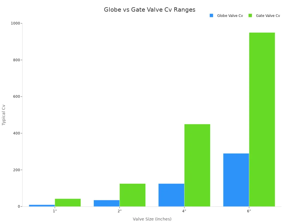
For every size, the gate valve offers much higher Cv. This means lower pressure drop and higher flow capacity. The globe valve gives up this capacity for precision. You must weigh this trade-off carefully.
TANGGONG VALVE designs its globe control valves to follow rigorous sizing calculations. This ensures the valve performs as specified for your process conditions.
The working principle of the globe valve combines linear motion with a deliberate flow restriction. This combination delivers the precise control that process industries need.
Common Globe Valve Types and Applications
T-Pattern, Y-Pattern, and Angle Valves
The T-pattern globe valve is the most common type you will see. Its name comes from the internal flow path that makes a sharp turn. This sharp turn creates more resistance and a bigger pressure drop. You get very precise throttling, but you lose energy. This design works well in less demanding systems where pressure drop is not a big issue.
The Y-pattern globe valve fixes this problem with a better design. Its seat and stem sit at an angle to the pipeline. This smoother path cuts turbulence and energy loss a lot. You can see the difference in the table below:
|
Parameter |
T-Pattern Globe Valve |
Y-Pattern Globe Valve |
|---|---|---|
|
Flow path geometry |
Sharp turn |
Angled path |
|
Pressure drop |
Higher |
Lower |
|
Energy efficiency |
Lower |
Higher |
|
Flow control precision |
More precise |
Moderate |
Y-pattern valves work well for high-pressure and high-temperature jobs. You will find them in oil and gas, chemical processing, power generation, water treatment, and pharmaceutical plants. The angle pattern valve gives you a third choice. It turns the flow at the valve outlet. You use this design on top of boilers or as chokes on oil well production units called Christmas trees.
Picking the Right Globe Valve for Your Needs
Your choice depends on pressure, temperature, and flow features. You must also think about the trim characteristic. Linear trim works best for systems with steady pressure drop. It suits liquid level control and steam pressure letdown. Equal percentage trim handles systems with changing pressure drop better. It excels at temperature and pressure control where the valve pressure drop changes with flow.
|
Factor |
Linear |
Equal Percentage |
|---|---|---|
|
System Pressure Drop |
Best for constant ΔP systems |
Best for varying/decreasing ΔP systems |
|
Valve Pressure Drop Ratio |
Use when valve takes a significant portion of system ΔP |
Use when valve takes a small portion of system ΔP |
|
Most Common Application |
Liquid level control |
Temperature and pressure control |
|
Sensitivity at Low Flow |
High (can be too aggressive) |
Low (precise micro-control) |
|
Sensitivity at High Flow |
Constant |
High (rapidly opens up) |
If you are not sure about exact piping friction losses, pump curves, or specific process dynamics, go with equal percentage trim. An equal percentage valve is very forgiving and stops PID loop instability.
TANGGONG VALVE offers globe control valves in a wide range of sizes and pressure classes to cover most industrial needs. You can match the valve size and rating to your specific process conditions.
Globe Control Valve vs. Gate and Ball Valves
Comparing Throttling Capability and Pressure Drop
When you pick a valve for your system, you must know the trade-offs between control accuracy and energy loss. Globe valves are great at fine flow control, but they cause a bigger pressure drop than gate or ball valves. Gate and ball valves are made for on/off use, not for steady throttling. A well-trimmed globe valve can adjust flow over a wide range, while a v-port ball design can reach an even wider range. But a normal ball type only gives a limited useful range.
|
Type |
Pressure Drop (relative) |
|---|---|
|
Globe |
High |
|
Gate |
Very low |
Pressure drop directly affects energy use. Any pressure lost in the valve must be made up by pumps or compressors. This raises power use and running costs.
Better trim lowers pressure losses and smooths flow changes, which cuts the power needed for pumping or compression. In many cases, upgraded trim leads to clear drops in energy use and operating cost.
The higher pressure drop of a globe valve comes from the twisty S-shaped flow path. Fluid must change direction many times, losing energy as it gets mixed up. This design gives you great throttling control, but you pay more for pumping. The control ability of these valves makes them perfect for steady regulation even with the energy cost.
Key Maintenance Considerations for Longevity
The seat and disc wear the most in a globe valve. Throttling exposes them to fast-moving fluid that can wear away the metal. Over time, this wear can cause leaks and lower control accuracy. Common failure modes include:
-
Wire drawing: Fast steam cuts a groove into the seat face.
-
Particle impact: Solids in the fluid hit the seat surface.
-
Flashing: Liquid turns into vapor, making fast droplets.
-
Cavitation: Bubbles pop and create tiny jets that eat away metal.
The stem packing is another spot that leaks often. You need to check and adjust it regularly. But many of these valves let you fix them in the line. You can change the seat and disc without removing the valve from the pipe. This is a big plus. TANGGONG's cage-guided trim design helps reduce wear and cavitation, making the seat and disc last longer.
TANGGONG VALVE tests its globe valves to rigorous industry standards and holds relevant certifications. This tough testing ensures reliable work and long life in tough jobs.
The globe control valve remains the top choice when you need precise flow control and throttling accuracy. Its linear motion and S-shaped flow path deliver exceptional regulation, though you pay for this precision with higher pressure drop.
When selecting a valve, weigh your need for accuracy against energy costs. If your process demands fine adjustments, the globe valve's benefits outweigh its drawbacks. For simple on/off service, consider other options.
Ready to find the right valve for your system? Consult the experts at TANGGONG VALVE for guidance on your specific application and explore their full range of control solutions.
FAQ
What is the difference between a control valve and a shut-off valve?
A globe valve adjusts flow for exact control and throttling. A shut-off valve only turns flow on or off.
What is cage-guided trim?
Cage-guided trim uses a cylinder with carefully made openings to guide the plug. It lowers noise, stops cavitation, and makes trim last longer.
How do you size one for your application?
You need fluid type, flow rate, pressure, and temperature. TANGGONG gives free sizing calculations.
What certifications do TANGGONG products have?
TANGGONG products meet relevant industry standards and certifications.
What is the difference between pneumatic and electric actuators?
Pneumatic actuators use compressed air for safe operation in dangerous areas. Electric actuators use a motor for exact positioning in automated plants.