



You check important measurements to protect factory pipes. Engineers match flow performance Cv and fluid movement. They also check heat limits. Putting in the right flanged check valve works. It stops bad backflow. It stops fast pressure jumps. It stops harmful water hammer. You must check daily pressure numbers. You check test standards. You check burst safety limits.
Choosing the correct check valve keeps systems safe. It meets work rules.
Key Takeaways
-
Use the STAMPED method for valve sizing.
-
Check the correct temperature rating and pressure limits.
-
Match valve body metals to your system fluids.
-
Also, match internal seal materials with these fluids.
-
Calculate cracking pressure for better safety.
-
Measure fluid velocity to keep valve discs stable.
-
This helps prevent fast part wear and tear.
-
Choose axial flow non-slam valves today.
-
They stop dangerous water hammer from happening.
-
This protects your factory pipes from damage.

The STAMPED Framework for Check Valve Selection
Engineers follow important steps. They check every system detail. The STAMPED method helps them choose wisely. STAMPED means Size, Temperature, Application, Media, Pressure, Ends, and Delivery. You set needs before buying parts. This careful check stops bad pipe breaks.
Sizing and Flow Coefficient Cv Requirements
You find the flow coefficient $Cv$. This calculation shows water volume and speed. The $Cv$ number tells how much water moves through. It measures gallons per minute with one-pound pressure loss. You use math rules. They show pressure drop across the body.
Flow Coefficient (Cv) Formula for Incompressible Liquids:
$Q = Cv \times \sqrt{\frac{\Delta P}{SG}}$
Dynamic rearrangement for pressure drop evaluation: $\Delta P = SG \times \left(\frac{Q}{Cv}\right)^2$
Key Insight: The flow coefficient helps build water flow models. High $Cv$ numbers mean low flow resistance. They lower system pressure loss directly. Small $Cv$ numbers mean higher flow resistance. They create larger pressure drops inside the valve.
|
Parameter / Relationship |
Mathematical Expression / Value Range |
Impact on Pressure Drop Calculations |
|---|---|---|
|
Cv to Kv Conversion |
$Cv = 1.156 \times Kv$ |
It puts metric flow numbers ($Kv$) into imperial pressure drop math formulas. |
|
Resistance Coefficient (Zeta / $\zeta$) |
$\zeta = \frac{2540 \times \rho}{Cv^2}$ |
It shows resistance ($\zeta$) drops as $Cv^2$ grows larger. |
|
Swing Check Valve Resistance Range |
$\zeta = 0.40 - 2.50$ (Size: 50–300mm) |
It gives tested resistance numbers for check valves during forward water movement. |
High $Cv$ numbers keep liquid moving well at all speeds.
Temperature Limits and Media Thermal Effects
You must check heat limits inside your pipes carefully. High heat changes body metal strength. It also hurts soft seal parts. Big heat makes metal expand. It makes soft seals weak too. You pick strong metal alloys for hot fluid lines. They keep seals tight.
Application Dynamics and Operational Limits
You check fluid speed and pump start times. Fast moving fluid can rattle valve discs. This shaking breaks parts early. You change spring tightness inside the mechanism. Stronger springs keep inner parts steady during low flow times.
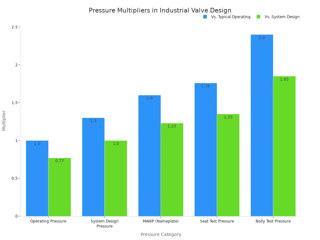
Pressure Parameters Operating Proof and Burst
You review four pressure limits to protect your pipes:
-
Standard Operating Pressure: Normal fluid force during daily work.
-
System Design Pressure: Top inner force pipes hold constantly.
-
Proof Testing Pressure: High factory test pressure checking body strength.
-
Burst Pressure: Extreme pressure point breaking body walls open.
You pick strong pressure limits. They must beat all surprise pressure spikes.
End Connections and Flange Profiles
You choose flanged pipe joints. They match pressure needs and job types. You pick Raised Face (RF) flanges. Or you choose Ring Type Joint (RTJ) flanges. Your process pressure guides the final choice.
|
Feature / Criterion |
Raised Face (RF) Flanges |
Ring Type Joint (RTJ) Flanges |
|---|---|---|
|
Sealing Mechanism |
Soft or metal-like gaskets squeeze flat or bumpy surfaces to stop leaks. |
A metal ring squeezes into a smooth groove to seal tight. |
|
Pressure & Temperature Limits |
Works fine in medium heat or force; high heat causes leak risks. |
Great for big force (ASME Class 900 ), high heat (>800°F/427°C), and changing loads. |
|
Flange Thickness & Material |
Needs thinner metal walls because it lacks deep grooves. |
Needs thicker metal and strong alloys to support deep grooves and tight bolts. |
|
Installation & Maintenance |
Fast and simple setups using common, cheap soft gaskets. |
Needs exact alignment and clean parts; bad setups ruin metal grooves. |
|
Cost Profile |
Cheap to buy and build; great for normal daily pipe jobs. |
Costs more for fine cutting and metal gaskets, but stops dangerous leaks later. |
You review safety factors when picking your flange shapes:
-
Operating Pressure & Severity: RF shapes suit simple jobs. RTJ shapes handle hard jobs above ASME Class 900 or heat past 800°F (427°C).
-
Safety & Criticality: RTJ metal rings seal better than RF gaskets on harsh chemical lines or hot steam pipes.
-
Industry Compliance: Strict API and ASME rules require RTJ shapes on dangerous, high-pressure setups.
-
Maintenance vs. Lifecycle Cost: RF joints cost less early on. Yet RTJ joints stop bad leaks and avoid long repair delays.
You make your final check valve choice after checking all safety rules.
Evaluating Media and Materials for a Flanged Check Valve
Fluid Viscosity Particulates and Slurries
Study media traits first. Big thick liquids slow down internal disc movement. Heavy slurries clog parts fast. Pick full-port flanged designs now. Smooth interior surfaces stop buildup. They keep fluid compatibility strong.
Valve Body Alloys and Cast Metallurgy
Choose top body material options. They handle high pipe stresses easily. Carbon steel gives great strong support. It helps general industrial uses. Stainless steel shows chemical compatibility. It stops acidic pipelines damage. Duplex alloys fight pitted corrosion. Match metal material well. Use correct fluid pressure needs.
Material Selection Tip: Check line fluid temperature first. Test pH levels too. Bad chemical compatibility ruins valve walls quickly.
Elastomeric and Metallic Trim Selection
Inner trim parts hold tight seal protection. Soft elastomeric seals stop leaks. They give zero-leak performance. Use them in low-pressure systems. Metal seats resist extreme heat. They fight abrasive particles too. Study your application environment. Pick good resilient material components. They satisfy system requirements. Strong trim options stop chemical compatibility issues. They stretch piping system lifespans.
Sizing Methodology and Cracking Pressure
Calculating Minimum Cracking Pressure
You found fluid flow speeds earlier. Now find lowest cracking pressure. Inner springs need small pressure steps. They lift the disc up. You count this force carefully. Fluid moves fast when pumps start. Right math satisfies system requirements well.
Engineering Tip: Test cracking pressure against baseline fluid force. Small pressure keeps valve discs trapped.
Pressure Drop and Full-Open Velocity
Fast liquid speed lifts inner parts. Velocity holds the disc open wide. Slow line speed makes discs chatter. Chatter ruins seats and adds friction.
Check line speeds against target flow rates. Fast fluid improves valve work. Low pressure drop saves power costs.
|
Velocity State |
Disc Position |
Operational Risk Level |
|---|---|---|
|
Below Minimum Velocity |
Partially Open |
High (Disc Chatter & Wear) |
|
Full-Open Velocity |
Fully Lifted |
Zero (Stable Flow Profile) |
|
Excessive Velocity |
Fully Open |
Medium (High Pressure Drop) |
Dynamic Stability in Variable Flow
Changing flows cause dynamic pipe problems. Engineers check valve speed during sudden reversals. Pick spring force using flow plans. Good springs stop disc shaking fast.
Study valve traits to stop shock waves. Right valve size protects piping system parts. Check valve status during slow flows. Test dynamic rules to keep lines running.
Mechanical Types of Flanged Check Valves
You pick flanged valves to stop backflow. Different designs move and close in special ways. You test these designs against your daily system needs.
       [ Swing Mechanism ]            [ Axial Flow Mechanism ]
    Fluid Flow ->  (  \ Disc       Fluid Flow ->  [Disc]===<Spring>
                   | Hinge                        (Linear Shaft)
Swing Check Valves
Swing valves use a hinged top disc. Forward fluid pushes the disc open. Returning fluid swings it shut again. These work well in slow, steady liquid pipes. But vertical setups cause big work problems:
-
Upstream Pressure Disruption: Downward flow lets fluid weight force discs open.
-
Dynamic Instability and Wear: Vertical pipes disrupt disc seating and shake parts fast.
-
Risk of Stalled Disc: Upward flow jams open discs at 90 degrees.
-
Strict Upward Flow Requirement: Vertical setups need strictly upward flow to work right.
-
Sluggish Disc Closure: Upward setups close slowly because they rely on gravity.
Piston and Lift Check Valves
Piston valves move inner discs up and down. High fluid pressure lifts the piston up. Gravity pushes it down to stop backflow.
Choose piston valves for high-frequency cycling applications. They handle severe pressure changes in steam systems. Built-in damping chambers cushion fast piston moves. This protects parts during continuous pump operation.
Dual-Plate Wafer and Flanged Valves
Dual-plate valves use two half-circle plates. A spring forces both plates shut fast. You buy these in compact flanged body styles.
|
Selection Metric |
Swing Check Valve |
Dual-Plate Valve |
|---|---|---|
|
Face-to-Face Space |
Wide body footprint |
Compact body width |
|
Response Speed |
Slower gravity closure |
Fast spring-assisted closure |
|
Pressure Drop |
Minimal flow restriction |
Moderate central turbulence |
Dual-plate styles save weight and pipe space. Twin springs spread force across both plates evenly. This design shuts smoothly inside small pipe layouts.
Axial Flow Non-Slam Nozzle Valves
Axial flow valves center discs on linear shafts. Heavy inner springs hold discs shut tightly. Forward fluid pushes discs down the main path.
Dynamic Responsiveness: Slowing fluid lowers dynamic forces on the disc. The inner spring pushes the disc shut fast. Short paths and spring help lower reaction times. This creates quick shutoffs and stops reverse flow.
Axial flow designs offer great surge protection:
-
Rapid Dynamic Reaction: Inner parts react to backflow right away.
-
Stroke Efficiency: Short travel distances close discs fast and stop water hammer.
-
Rapid Closure Requirement: Quick closing stops high backward flow speeds.
-
Design Optimization Factors: Low friction and short travel paths stop valve slam.
These strong traits make nozzle valves best for critical, high-energy liquid applications.
Flange Standards and Pressure Classes
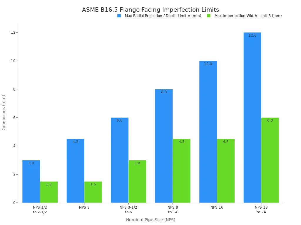
ASME B16.5 Facing Profiles and Dimensions
You check flange faces to stop pipeline leaks. ASME B16.5 sets exact surface finishes. Tools cut spiral grooves in Raised Face profiles. Ring Type Joint grooves need smoother faces. Flange sizes grow with bigger pipes.
ASME Pressure Classes 150 through 2500
You pick pressure classes matching line limits. High heat weakens metal body walls. It lowers safe pressure limits quickly. Class 150 steel holds 285 psig at 100°F. High heat lowers this limits to 80 psig. Strong lines use Class 1500 valves.
|
Pressure Class |
Rating at 100°F (psig) |
Rating at 400°F (psig) |
Rating at 800°F (psig) |
|---|---|---|---|
|
Class 150 |
285 |
200 |
80 |
|
Class 300 |
740 |
635 |
410 |
|
Class 600 |
1480 |
1265 |
825 |
|
Class 1500 |
3705 |
3170 |
2055 |
|
Class 2500 |
6170 |
5280 |
3430 |
API 594 API 6D and ASME B16.34 Standards
You check standard design rules before building. Factory codes set rules for check valves. You choose flanged parts using clear trade guides.
-
ASME B16.34 Non-Destructive Testing: Tests inner body metal strength. Sound waves find hidden inner metal cracks.
-
API 6D Operational Testing: Requires full water pressure checks. It tests shell and seat leak safety.
-
API 594 Dimensions: Sets compact flanged valve sizes. It tests air seals using API 598 rules.
You match these design rules with system requirements. This keeps systems safe for many years.
Installation Dynamics and Water Hammer Mitigation
Horizontal and Vertical Piping Constraints
Put a flanged check valve in the right direction. This keeps liquid moving safely. Most valves work fine in flat lines. Straight up lines need more care. Gravity pulls hard on inner valve parts. Pick spring check valves for upward flow. Downward flow ruins seats and drops pressure.
Transient Pressure Surges and Water Hammer
Sudden pump stops cause bad shock waves. Water hammer breaks pipes and tools quickly. Stop fast pressure spikes using quick non-slam valves. Springs shut valve discs before flow turns around.
💡 Key Dynamic Insight: Fast closing stops quick backward flow. This speed saves pipe joints and parts.
Fast closing keeps valves working well everywhere. You follow safety rules and stop costly delays.
Upstream and Downstream Pipe Run Limits
Pipe bends create messy liquid swirls inside. Put straight pipes before valves to stop swirls. Make straight pipes 5 to 10 diameters long. This creates smooth flow before touching inner parts. Never place valves right next to pumps. Do not place them near control valves. Good spacing stops disc shaking and early wear. Keep 3 to 5 pipe diameters downstream too. This steady distance keeps liquid pressure safe.
Good valve choice needs right shapes for flow needs.
You pick a flanged check valve carefully. You balance quick response, crack pressure, and safe seals. Smart workers size parts right. They do not just match pipe sizes. You test system numbers and meet work needs. Lastly, you check flow changes. This action shields pipes from big shock waves.
FAQ
How do you prevent water hammer in flanged check valve systems?
Pick fast axial flow designs. Inner springs shut discs before fluid reverses. This stops bad shock waves in pipes. Also, keep straight pipe runs upstream.
When should you select a flanged end connection over a wafer body?
Pick flanged connections for high-pressure systems needing maintenance. They allow easier removal and bolt alignment. They handle severe pipe stresses better than wafer valves.
Why does cracking pressure matter for your check valve performance?
Cracking pressure sets the lowest opening force needed. Match this number to your pump specs. Right sizes stop valve chatter during low flow.
💡 Selection Tip: Size valves using dynamic flow profiles, not pipe sizes.
How do you size a valve to achieve full disc stability?
Find flow coefficient $Cv$ using velocity and pressure drop limits. Do not just match valve size to pipe diameter. Dynamic sizing lifts discs fully to stop wear.