



Based on recent reports, the global market for cage type single seated control valves hit 3.0 billion dollars in 2024.
You can use these straight-moving valves with special inner cages to guide plugs and control fluid flow. Heavy pipe systems often suffer from big pressure drops, shaky plugs, rough fluid motion, loud noise, and wear. The working principle of a cage control valve fixes these problems by providing smooth flow control, exact pressure adjustment, and safe shutoff per ANSI/FCI 70-2 standards. Using a strong cage-guided control valve keeps your important fluid systems steady and working safely. With more than 36 years of experience, TANGGONG VALVE builds smart valve products for modern industrial plants.
Key Takeaways
-
Cage control valves guide inner plugs to manage fluid flow smoothly.
-
Special metal cages prevent the plug from shaking violently and help lower loud noise.
-
Balanced plug designs use inside holes to lower the power an actuator needs.
-
Special cage openings create straight or evenly balanced paths for liquid to move through.
-
Strong metal trim materials keep internal valve parts safe from wearing out quickly.
-
Workers can easily trade out inner cages inside the pipe to change how fluid flows through the system.
-
Power stations and oil refineries depend on cage valves for tough jobs.
Understanding Cage Control Valve Components and Trim Design
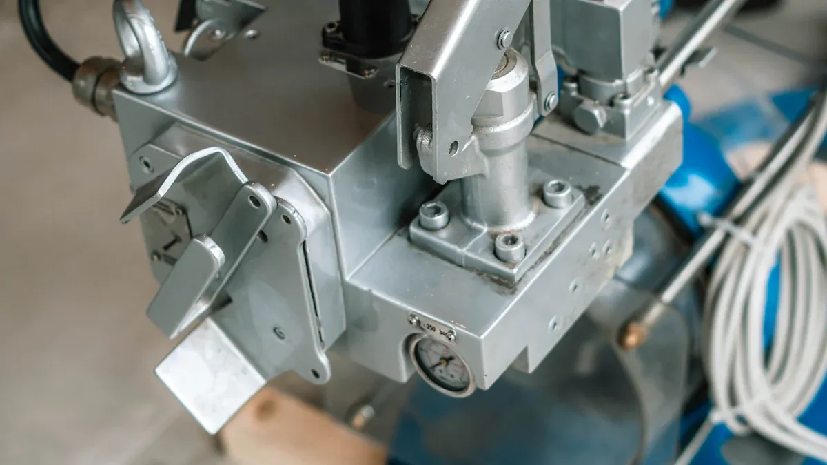
You pick a valve body design by looking at fluid movement and pressure levels. TANGGONG VALVE makes these parts with cast steel like WCB for normal jobs, WC6 for high heat, and CF8 or CF8M stainless steel for liquids that rust metal. You can select from two main body shapes to handle heavy operational stress.
In standard globe valves, fluid changes form as it passes through the port and sends a fast stream straight into the valve wall. Angle and eccentric plug valves let fluid leave directly without turning anywhere. These designs protect the valve body by letting fluid expand right into the downstream pipe.
Main Pressure Containment Body
Globe and Angle Body Geometries
Globe bodies have balanced inner spaces that easily hold thick cage parts. You can install angle bodies to handle big pressure drops, boiling liquids, or rough mud mixtures. Choosing the right body shape guides fluid smoothly through the flow zone while keeping the pressure safely inside.
End Connections and Flange Ratings
You connect the outer valve shell to your pipes using standard connector parts. Factory workers build these valve bodies to handle strong pipeline stress across ratings from Class 150 to Class 2500. Flanged ends help workers install or remove valves quickly during planned factory repairs. You can also pick welded ends for high-pressure systems. Tight joints stop dangerous leaks and keep parts lined up correctly when temperatures change.
Precision Trim Assembly Parts
Cylindrical Cage with Engineered Ports
The round metal cage serves as the main part for managing fluid flow. Carefully cut openings in the cage wall shape the fluid stream as the inner plug moves up and down. You can pick special opening shapes to get steady, equal percentage, or fast-opening fluid movement. TANGGONG VALVE makes inner parts using SS316, 17-4PH, Stellite 6 coating, or Tungsten Carbide. These strong metal materials endure harsh temperatures from -196°C to 650°C in rough work settings.
Balanced and Unbalanced Valve Plugs
You need to pick between balanced and unbalanced plug types based on your system pressure differences. Unbalanced plug designs do not have any balance holes inside the plug unit. Because of this, total fluid pressure pushes directly against the plug surface, requiring strong stem power equal to force times area (F = PA).
|
Feature |
Balanced Valve |
Unbalanced Valve |
|---|---|---|
|
Shutoff Quality (Sealing) |
Good, limited (Class II-IV) |
Excellent (Class V-VI) |
|
Pressure Handling (Flow capacity in high-pressure drop) |
Excellent, suitable for high-pressure drop |
Poor, limited by actuator force |
Balanced plugs include inner holes that equalize liquid pressure throughout the unit. These small channels equalize fluid pressure above and below the moving plug. This clever design cuts down required actuator force while keeping operation steady during big pressure drops.
Bonnet, Stem, and Sealing Elements
Packing Box and Stem Guidance
The bonnet seals the top section and holds the stem seal assembly. You use the packing box to stop gas leaks around the moving control stem. Strong PTFE or graphite packing rings seal the stem area to keep liquids inside. The outer cage guides the plug along its entire surface at all times. This firm setup stops side movement, stem bending, and plug shaking during heavy flow control.
Seat Ring Integration and Leakage Classes
The seat ring works alongside the plug to stop fluid flow entirely when closed. You must match the seat layout with your required ANSI/FCI 70-2 shutoff class to keep proper system control.
-
Standard metal plugs on metal seats give Class IV shutoff for normal plant operations.
-
Fine-tuned metal seating with high actuator push achieves tight Class V shutoff for tough jobs.
-
Soft seal inserts made of rubber or plastic give bubble-tight Class VI shutoff.
Different factory designs meet varied process needs. Plant engineers test many control valve types before choosing parts for severe conditions. Basic valve models need exact stem positions to keep the entire system stable. A correctly built cage control valve gives accurate flow management and protects downstream tools. You maintain full process control through changing pressure loads by matching valve metals to fluid traits. Advanced trim design lowers repair needs and extends overall valve life. Accurate industrial control protects your plant equipment while increasing total output. You keep your cage control valve running well through strong construction methods. Every single control valve provides precise flow control when built correctly. Picking a high-performance control valve improves operational output quality across your facility.
Working Principles of a Cage-Guided Control Valve
Throttling Mechanism and Flow Dynamics
Plug Movement Inside Stationary Cage
You see how a cage control unit works when its actuator moves the plug inside a stationary cage. Fluid enters the main valve body and flows straight into the round metal cage structure. As the actuator adjusts the stem, the plug moves up and down to cover or uncover cage openings. This mechanical movement controls how much liquid moves through internal passages.
In this control valve, the full cage surface holds the plug across its entire travel distance. This firm internal setup keeps the plug and seat ring lined up. Constant contact stops parts from scraping and keeps liquid from leaking around flow paths during normal plant work.
Variable Flow Passages and Area Opening
The shape of the ports cut into the cage wall sets your overall system flow capacity. As the plug rises, it opens up a set geometric area to control process volume.
Cage trim can be designed for linear, equal-percentage, or even noise-attenuating characteristics. The bottom line: three characteristics, two real choices (linear or equal percentage; quick open is on/off-adjacent).
Different factory uses need clear trim profiles to handle system fluid movements correctly.
Cage-guided globe valve trim characteristic is a function of port shape. As the plug rises up, the amount of port area uncovered determines the shape of the characteristic graph.
You can pick from three main trim setups based on your plant process needs:
-
Linear characteristic ports expand the flow area at a steady rate relative to stem travel distance.
-
Equal percentage ports grow the flow area faster to handle big pressure changes across the pipe.
-
Quick-opening ports clear the main passage area right away for rapid liquid discharge.
High-Performance Flow Control in High-Pressure Systems
Pressure Drop Dissipation Mechanics
You use strong flow control to handle big pressure drops without hurting internal valve parts. Standard single-seat valves send fast liquid right against inner walls, causing quick wear. The strong cage splits the liquid stream into several small jets. These meeting streams clash in the middle of the cage space.
The hitting fluid jets lose energy inside the cage before touching the main body shell. This internal setup shields outer body materials from harsh liquid forces. You keep your process steady and prevent damage during big pressure drops.
Elimination of Lateral Plug Vibration
High pressure differences make strong side forces inside large plant pipe networks. Top-guided designs often shake violently when fluid flow gets rough. The cage-guided valve stops this operation hazard by using continuous outer rim contact.
The inner cage wall supports the moving plug across its entire outer diameter. This full surface contact takes in side impacts and calms the moving stem assembly. You avoid bent stems, seal wear, and loud noise during heavy flow work.
Pressure Balancing and Actuation Force
Internal Pressure Equalization Ports
Moving heavy valve trim against high pressure differences usually takes huge actuator power. Balanced cage plugs fix this physical problem by using inner pressure channels. Small holes run top to bottom straight through the solid plug body.
Process liquid moves through these holes to fill the space above the plug. Fluid pressure on top of the plug equals pressure below it. This balance cancels out heavy fluid forces pushing against the moving plug face.
Reduced Actuator Thrust Requirements
You choose smaller actuator packages when using pressure-balanced trim across your plant network. Because inner ports balance liquid forces, the actuator only fights packing friction and seat sealing resistance.
You can pair these balanced designs with different actuator types, like:
-
Pneumatic diaphragm actuators for quick fail-safe emergency steps.
-
Pneumatic piston actuators for maximum force output inside tight spaces.
-
Electric motor actuators for exact digital control without air supplies.
-
Electro-hydraulic actuators for top positioning accuracy under huge mechanical loads.
Smart positioners read digital signals like 4-20mA, HART, or Modbus to move these actuators smoothly. You lower total power use while keeping fast response speeds across main process lines.
Key Industrial Applications and Field Deployments
Process plants rely on heavy equipment to manage high pressure and flow. You can deploy cage units across various industrial applications to maintain system safety.
Severe service environments demand robust trim designs. The top three industries using cage valves for severe service include:
-
Petrochemical
-
Power
-
Refining
Oil, Gas, and Petrochemical Processing
Upstream Choke and Pressure Reduction
You face massive pressure drops in upstream gas production. Cage trim shields the valve body from high-velocity gas jets. You maintain precise flow control while preventing body wear.
The cage geometry splits high-velocity streams into smaller paths. This design dissipates fluid energy inside the central chamber. You protect downstream headers while ensuring stable wellhead output across industrial applications.
Refining Process Stream Throttling
Refineries require continuous flow control in distillation columns. You install cage units to stabilize process streams under changing line pressures.
These key applications depend on durable materials like 316 stainless steel for acid handling. You prevent valve trim wear by picking trim 10 for sour gas handling in refining applications.
Power Generation Facilities
Boiler Feedwater Throttling Service
High-pressure boiler systems require exact water delivery. You rely on a specialized control valve to handle high pressure drops without trim destruction.
Solid cage walls shield internal valve structures from steam and cavitation damage to prevent erosion-corrosion. You select GF TFE sealing rings for room temperature or graphite for high-temperature conditions. Metal seals handle process temperatures above 600°F. The protected inside seat moves seating surfaces out of direct flow paths to prolong trim life.
Steam Turbine Bypass and Attemperation
Steam bypass systems dump excess energy during power grid dropouts. You use anti-cavitation cages with larger flow paths to pass entrained particulate matter without blockage.
This flow setup reduces noise levels during rapid steam expansion. You protect turbine blades and secure steady temperature control across steam headers.
Chemical and Heavy Process Operations
Severe Service Corrosive Fluid Modulation
Chemical plants transfer harsh acids through piping networks. You deploy custom trim materials to resist chemical attack in demanding applications. Alloy 20 provides resistance against sulfuric acid in fertilizer plants. You can specify trim 12 with Stellite facing for high-temperature corrosive applications.
Proper material review prevents body leaks. You secure long-term process control while keeping maintenance crews safe.
High-Temperature Thermal Fluid Control
Thermal oil loops transfer heat in reactors. You use balanced cage trim to maintain continuous process control at peak operational temperatures.
These key applications require precise stem guidance across thermal conditions. You prevent plug binding and eliminate stem vibration during thermal fluid control.
Modern operators select cage designs for critical fluid control. You expand plant production efficiency across key industrial applications when matching trim styles to fluid traits. A high-performance control valve improves safety across harsh field applications.
Key Advantages and Selection Criteria
Acoustic Noise Reduction and Anti-Cavitation
Multi-Stage Cavitation Mitigation Cages
You keep liquid systems safe by stopping harmful vapor bubbles from forming. Special multi-stage cages lower fluid pressure bit by bit. This slow pressure drop stops quick liquid flashing when pressure falls sharply.
TANGGONG VALVE builds custom inner parts for pressure classes from Class 150 to Class 2500. These internal cages keep liquid moving smoothly and protect your machinery. You get reliable, high-performance flow control inside heavy pipe networks.
Sound Energy Dissipation Geometry
Strong fluid squeezing often makes loud sound shaking in gas lines. Smart cage openings break single gas streams into tiny jets. These small gas streams spread out sound energy inside the main valve space.
A controlled, multi-turn flow path dissipates energy gradually. It may provide strong control valve noise reduction in clean severe-service applications, but narrow paths can be unsuitable for dirty fluids or larger particles.
Maintenance and Trim Interchangeability
Quick-Change Inline Maintenance Features
You lower factory downtime by using top-opening valve designs. Repair crews easily take off top cover bolts to reach inside parts. You pull out the seat ring and cage without cutting the valve body from the pipe.
This easy design makes regular service simple in tough factory setups. Plant teams clean inside valve parts quickly during planned work stops.
Modifying Flow Characteristics in the Field
Factory needs often change over time as plant output moves up or down. You swap the inner cage to change flow control behavior right away. Plant workers switch between linear, equal percentage, or quick-opening flow shapes without buying new valve bodies.
This quick parts swapping lowers extra store costs for spare parts. You keep exact control over your system while spending less money.
TANGGONG Control Valve Engineering and Selection Criteria
IEC 60534 Sizing and Flow Coefficient Calculations
You get free IEC 60534 sizing advice straight from TANGGONG experts. Factory engineers run exact flow number calculations for your exact fluid needs. Right control valve sizing stops sudden bubble damage and ensures long product life.
Every cage control valve leaves our Wenzhou factory fully set for work. We test all goods using API 598 rules and hold ISO 9001:2015 quality badges.
Material Selection for Demanding Operating Conditions
You pick strong metals like WCB, WC6, CF8, and CF8M for valve bodies. Our workers supply special stem seals to meet ISO 15848-1:2015 leak rules and Quad O limits.
We sell a NACE-rated cage-guided control valve option for sour jobs with toxic gas. You keep safe pressure control and protect the environment across all main jobs.
markdown
You protect heavy piping systems by selecting a high-performance cage control valve. Full rim support stops plug vibration during severe pressure drops. Internal channels equalize liquid forces above and below balanced plugs. These smart features cut actuator power needs and stabilize high-pressure liquid streams.
Precision cages shape flow characteristics, while heavy-duty actuators deliver reliable stem positioning for accurate throttling. TANGGONG VALVE provides custom-engineered trim solutions certified to ISO 9001:2015, CE, and ANSI/FCI 70-2 standards. As a global leader with over 36 years of experience, we deliver every cage-guided control valve with factory-calibrated precision. Choose our advanced valve designs to boost system safety and maximize operational output.
FAQ
What is a cage-guided control valve?
A cage-guided control valve uses an inner metal tube to guide its moving plug. The cage has cut openings that shape how liquid moves. This design stops plug shaking, lowers noise, and handles big pressure drops in plant pipes.
How does a cage control fluid flow inside process lines?
You adjust the valve stem position by using a power actuator. As the stem moves the inner plug up or down, it uncovers cage ports. This movement changes the open area to give you exact pressure and flow control.
What are the main types of control valves used for heavy throttling?
Engineers pick globe, angle, and rotary valves for heavy flow control. Among these types of control valves, cage-guided models work best in tough jobs. They offer balanced plugs to handle pressure drops and high heat safely.
Which industrial applications benefit most from cage control valves?
You use these valves in tough oil, gas, power, and chemical jobs. They handle high-pressure boiler water, initial gas pressure drops, and harsh liquids. Their strong inner parts prevent quick wear and bubble damage in hard service.
Can you change the flow characteristics of a cage valve in the field?
Yes, you can change the flow style very easily. Repair teams remove the top bonnet and swap the inner cage inside the pipe. You switch between linear, equal percentage, and fast-opening cages to match new factory needs.
What actuation options can you use with these valves?
You can power your valve with pneumatic diaphragm, piston, electric, or hydraulic actuators. These drivers get standard 4–20 mA or digital signals. They give strong pushing force to keep the plug steady under high line pressure.